Labradar recoil trigger DIY

Thanks, Taff. That's what I have found with my field tests. I used the medium sensitivity and it worked fine with a heavy .22lr rifle, a .22 pistol and a Glock 9mm. As you said cocking did activate it but it worked fine with and without a capacitor.

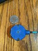
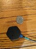
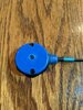
Here's a picture of it mounted to my 10/22

IMG_20201027_144228_429.jpg

Unfortunately, my 22/45 pistol has no rail, so I just taped it to the gun.

IMG_20201027_144228_430.jpg

After all we're just detecting the recoil not trying to do any measurements.

Oh and on the G17 the recoil did tend to move my simple plastic clamp mount around. Not a big deal as the switch doesn't care about orientation.

SO: Thank you Peels and Taff for this fun side trip back into electronics. Thanks Peels for finding these switches.

Long story short: Do what Taff did. Just solder a shake switch across the tip and ring of an 1/8" stereo jack. Personally, i'd go for the medium sensitivity switch. Sensitivity settings don't matter for using the switch.
 
Al,

The idea of going straight off the switch/sensor without extra components is from one of the guys over on the 6.5Grendel forum. Prior to that I was using a capacitor and resistor thinking this is what was needed to smooth the trigger impulse, but not needed - the radar subordinates this to its 2 second delay.

5564 - Copy.jpg This still works but the simplicity of just using the sensor by itself is obviously better.

Two methods of clamping specific to Picatinny rails;
A plastic rail cover
Cheap EBay bubble level.

jvcgu6ttx3yr - Copy.jpg rifle - Copy.jpg


More recently I just elastic band it to the scope or jam it in somewhere.
 
Last edited:
Taff, where were you 3 months ago? Could have saved me some time! :)

As I said in my first post. Part of the fun was figuring things out. alfsauve just took it too another level! I appreciate you guys sharing and confirming my observations.

I concur. Using the shake switch straight up should be fine.
 
Peel,

Apologies, but I've only just joined and only because I stumbled across your thread.

Yes, the switch by itself and an elastic band works fine.

On a related topic and you guys might be able to advise me here. I use a Li-ion rechargeable external battery to power the radar. It is a 2S so 8.3V DC when fully charged down to 6V when the protection circuit kicks in. I currently use a voltage regulator to buck the voltage to 5V which is the standard for a USB port. I've been wondering whether the port would take the full 8.3V (without the regulator). I figure there must be some sort of internal voltage regulation as the battery compartment takes 6xAA batteries (assuming series = 9V).

I asked the sales rep a while back for the voltage range and he said it was confidential information. I had the impression he had no clue and was covering his pride.

Can I connect without the regulator? Is there a way to figure out the voltage range of the radar without destroying it?
Battery Pack - Copy.jpg
 
Taff, 5V USB power packs are so cheap and plentiful, I wouldn't think it worth the effort to use something else.

While the internal battery pack of the LR might by 9V it could have it's own regulator to bring that down to 5V. The problem is that the micro-USB port might be downstream of that regulator. You could connect your 8V battery in place of the AA batteries and see if it works that way. That should be a low risk experiment. Wouldn't be hard to wire an external connector to the batter compartment if you want to keep using your 8V pack.

At the 2019 IRC they was running chronograph checks on a LabRadar that was powered by internal batteries. Of course it was on my turn that the readings were so far off everybody in line was shaking their head in disbelief. Fortunately, before the RO disqualified me, the LR screen flashed "low battery." After changing the batteries my ammo was retested and passed well above minimum PF. Point is there is a point below which LR will operate but will not give accurate readings.
 
Peel,
On a related topic and you guys might be able to advise me here. I use a Li-ion rechargeable external battery to power the radar. It is a 2S so 8.3V DC when fully charged down to 6V when the protection circuit kicks in. I currently use a voltage regulator to buck the voltage to 5V which is the standard for a USB port. I've been wondering whether the port would take the full 8.3V (without the regulator). I figure there must be some sort of internal voltage regulation as the battery compartment takes 6xAA batteries (assuming series = 9V).
View attachment 952977

It is not 9 volts.
Your assumption is wrong.
They split the 6 batteries 4.5v and wire in parallel so the voltage stays the same and the amperage goes up with more capacity.

Ask me how I know.
I purchased a new unit weeks ago and voided my warranty taking the tamper sticker off and opening it up for a update.

Hope this helps.
 
Last edited:
I purchased a new unit weeks ago and voided my warranty taking the tamper sticker off and opening it up for a update.

Ok, I'm curious. What did you update that required opening up the unit?
 
It is not 9 volts.
Your assumption is wrong.
They split the 6 batteries 4.5v and wire in parallel so the voltage stays the same and the amperage goes up with more capacity. ....
Hope this helps.

That changes everything.

But again, USB power packs are so cheap and plentiful why mess with any other power source.
 
Esok,

Why did you open it up? What did you do?

Al,
Yes, USB battery packs are cheap and cheerful but I have plenty of spare 18650's and in this case 32650's. I shoot mostly at night when you have the range to yourself but you need lighting, hence the batteries. The 2S2P 10Ahr 7.2V pack was spare and now it powers the radar with a voltage regulator.
 
Nothing major.
I have never been a fan of the micro USB connection, they are cheap and flimsy and definitely not up to the task in my opinion.

I am installing a 5.5x2.5 jack and using a 5.5x2.5 / USB cord to be used with a 5 volt battery pack.
I plan on installing this bulkhead plug and soldering wires directly to the wire tabs on the unit.
It should be able to handle direct 5 volts as the 4.5 volts is only .5 volt difference .
This will replace the AA batteries.
 
Just to add some data. I used the above method to make a recoil sensor. The labradar mic was not 100% reliable when shooting my ruger precision 22lr suppressed. I'm using it to practice with my rangefinder linked to applied ballistic software and wind meter. So I needed good data to plug into my firing solution. EZ enough to make, but the medium sensor would not trigger for me. I had to go with the high sensitivity sensor to trigger reliably. I also ordered the wrong 3.5mm plug by mistake. It has to be a 3 pole stereo not two pole even though you are only going to use the tip and middle. 2 pole won't work. If your wondering what I made my case out of, it's a cap from the tube a BCG came in and one of those caps that come on the end of tipton cleaning rods. Strain relief salvaged from network cable. Just some 3m dual lock velcro to attach it. Epoxied the internals to help with false triggers. Works well. Thanks for doing all the hard work guys.
 

Attachments

  • PXL_20210129_203110236.jpg
    PXL_20210129_203110236.jpg
    139.8 KB · Views: 31
  • PXL_20210129_200229436.jpg
    PXL_20210129_200229436.jpg
    154.9 KB · Views: 28
  • PXL_20210129_195916634.jpg
    PXL_20210129_195916634.jpg
    132.1 KB · Views: 28
Vibration/recoil trigger is where it's at, so for about $3 made my own. Whipped up the housing in Fusion 360 and then printed it, pulled a 3 pin aux cable out of a drawer, bought some vibration sensors, and voila.

Vibration sensors.

Cut off one end, strip to expose wires. The vibration sensor is tucked into the middle of the knot, showing the center post wire and thinner coil wire.

1ejoJHT.jpg

Testing fit in cavity.

5mqjTTD.jpg

Solder tiny f'ing wires to tiny f'ing wires. Test wires with a meter on continuity. The ring at the base of the plug is ground, figure out which wire is ground, cut it off. The other two are L and R (in my cord those were the red and white wires, yellow was ground), doesn't matter which solders to which on the sensor, because all it's doing is completing a circuit when the gun recoils.

UXXPVcX.jpg

Bend sensor wires down to the sides, wrap in electrical tape.

gUamMTf.jpg

Apply heat shrink, put some glue/epoxy down in hole, stuff wires into hole, then cap off with epoxy putty.

1iO7vF9.jpg

Goes on any rail, cross bolt is common 8-32 cut to length.

PBt84RM.jpg

XWp7TEd.jpg
 
Nicely done 10 ring! :thumbup:

I did the same thing...but printed the pic rail mount in ninjaflex so I can just snap it on and off.
 
Finally had some free time to play with a couple of 555 timers to setup the monostable trigger that @Clavdivs recommended above. I chose a resistor/capacitor combo that would give a 0.25 second trigger time. Figure that is plenty of time to hold the trigger voltage high to trigger the labradar while allowing the shake sensor to settle down. Once I got it all put together, the sensitive shake switch was able to trigger on very slight taps (even when moving it sometimes). The medium sensitivity shake switch appears to work much better than just using the switch alone.

But then I though....why stop here?? :p

I decided to add an electret mic to the circuit (along with a LM393 comparator) so I can chrono my PCP air rifle also. The sound level to trigger can be adjusted via a potentiometer. I expect neighboring shooters to set off the sound based trigger at the range, so decided to added a simple slide switch so I can disable the sound based triggering in those situations.

Have not had a chance to try it out at the range yet, but was able to confirm the sound from a PCP is able to trigger properly. Dropping an AR bolt on an empty chamber also triggers nicely. Will probably have to wait for warmer weather before I will get a chance to test it out in the wild.

Recoil_trigger_Completed1.JPG

Recoil_trigger_internals1.JPG
 
I use a 3.5mm socket to house the vibration switch. Same size as a AA so stows inside the battery compartment with its cable. I use an external battery so that compartment is where it stays.

Nothing fancy to attach it to the gun other than an elastic band.

Settup.jpg Stowage - Copy.jpg Switch and Housing - Copy - Copy.jpg
 
Last edited:
Vibration/recoil trigger is where it's at, so for about $3 made my own. Whipped up the housing in Fusion 360 and then printed it, pulled a 3 pin aux cable out of a drawer, bought some vibration sensors, and voila.

Vibration sensors.

Cut off one end, strip to expose wires. The vibration sensor is tucked into the middle of the knot, showing the center post wire and thinner coil wire.

View attachment 990584

Testing fit in cavity.

View attachment 990585

Solder tiny f'ing wires to tiny f'ing wires. Test wires with a meter on continuity. The ring at the base of the plug is ground, figure out which wire is ground, cut it off. The other two are L and R (in my cord those were the red and white wires, yellow was ground), doesn't matter which solders to which on the sensor, because all it's doing is completing a circuit when the gun recoils.

View attachment 990586

Bend sensor wires down to the sides, wrap in electrical tape.

View attachment 990587

Apply heat shrink, put some glue/epoxy down in hole, stuff wires into hole, then cap off with epoxy putty.

View attachment 990588

Goes on any rail, cross bolt is common 8-32 cut to length.

View attachment 990589

View attachment 990590
@10 Ring Tao
Would you mind sharing the file for your housing?
 
Being electronically challegened, we bought one for 35 bucks and attach it with a rubber band.

We do a lot of suppressed shooting and found it necessary to get reliable results.

The downside of the store bought one is it will trip when a bolt action is cycled.
 
Thanks Alf, but to be fair the same size as a AA was just luck.

Duke,
The false firing thing is something we all have to live with. I just ignore it and carry on cranking that bolt like a one-arm bandit at a casino. The radar keeps giving that message screen that it can't see a bullet and to press a button to reset, I ignore it. Just carry on shooting and it will reset itself. I don't even know why they have it.
 
Last edited:
Back
Top