Any Engineers Here? (With access to a 5-shot J-Frame)

Status
Not open for further replies.

lvalmont

Member
Joined
Sep 19, 2010
Messages
38
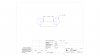
I need the measurements of the red lines.

I have digital calipers and have approximated measurements....I just want something more precise.

help.jpg

For those interested: Working on making a speed loader. I know I can buy one, just bored this spring break.


Thanks in advance!
 
Measuring centerline to centerline is tough and requires a good eye to be accurate. If you measure edge to edge you'll be more precise and, since each chamber is the same diameter (ideally!) the edge-to-edge and center-to-center dimensions are equal.
 
As stated, edge to edge is the standard method when reverse engineering something like this (I reverse engineer many parts for my job). Measuring to the edge will give you the distance between the holes, then the equation is simply Edge + Diameter = Center Distance
 

Attachments

  • Draw1.JPG
    Draw1.JPG
    51.5 KB · Views: 63
Most software EULA's specify that their software cannot be used to "Reverse-Engineer" which is what you are doing. If you are using software and you happen to also use a Microsoft Operating System, Microsoft makes it clear in the OS's EULA that you will NOT be using the operating system that is in any way illegal.

I would think that this begins to borderline on "illegal" however I am not the one to determine that, that would be between whatever software you used to make your drawing and your relationship with Microsoft (or any other OS you may be using).

If you go against Microsoft's EULA, you will no longer be protected by their updates, even though it looks like you are being updated. It states that right in the EULA.
 
Read the EULA again. you agree not to reverse engineer microsoft products.


I measure inside edge to inside edge and outside edge to outside edge and then average them (i also reverse engineer for a living), but its really six of one. If i can get at my J-frame, i'll get the measurement for you.
 
I came up with .850 on the long line.
I measured the OD of 2 holes side by side.

High tech .... paper, pencil make rubbing.
 
Last edited:
Method A: Use the "inside" measurement feature of the calipers.

Measure outside edge to outside edge between two of the holes. (stick the calipers in the holes and open them as far as you can)

Measure inside diameter of one hole and subtract that number.

Method B: Use the calipers as normal, measure the shortest distance between the two holes (stick the calipers in the holes and close them ass much as possible.

Measure inside diameter of the hole and add it to the first number.
 
Using a 85 Taurus I got 0.823 on the long line and 0.511 on the short line. I will measure a speedloader tonight and see if I get the same dimensions. I used (outside dimension + inside dimension) divided by 2.
 
I am using edge to edge - diameter of one hole, but I can't seem to get consistent readings. If i stick the caliper even a fraction of a millimeter deeper into the cylinder, the measurement changes on me.
 
Last edited:
The inner dimension is harder to hold. I will measure the speedloader and a Smith J frame. I'll have a better idea tomorrow. I have more measuring tools in my desk at work. Specifically my small calipers. I will try to get the center diameter of the holes and the angle from center of each hole. That should let you know where to put your holes. Building a speedloader actually sounds like a fun project.

Added: The angle from center of each hole is simple: 360/5=72 degrees
 
Last edited:
Most software EULA's specify that their software cannot be used to "Reverse-Engineer" which is what you are doing. If you are using software and you happen to also use a Microsoft Operating System, Microsoft makes it clear in the OS's EULA that you will NOT be using the operating system that is in any way illegal.

I would think that this begins to borderline on "illegal" however I am not the one to determine that, that would be between whatever software you used to make your drawing and your relationship with Microsoft (or any other OS you may be using).

If you go against Microsoft's EULA, you will no longer be protected by their updates, even though it looks like you are being updated. It states that right in the EULA.

LOLS!!!! That's about software, dude, as stated before.

Besides, he's not reverse engineering any commercial product, anyway - if he was, it would be the cylinder of the revolver. He's engineering a speedloader for it. :D

Trying hard not to spew water all over my desk here. LOL!!
 
I think we all assumed that a 5 shot j-frame equates to 38/357 caliber. If the OP had specified 6 shot j-frame we would need to ask 22 or 32. Good point though.
 
For finding the CTC measurement, caliber is not required. Measuring the same edge of any two holes will give the CTC measurement.
 
LOLS!!!! That's about software, dude, as stated before.

Besides, he's not reverse engineering any commercial product, anyway - if he was, it would be the cylinder of the revolver. He's engineering a speedloader for it. :D

Trying hard not to spew water all over my desk here. LOL!!
OK, sorry, folks, for being too picky.
I guess you could say "take what I say with a grain of salt!"

LOL,
Thank you for setting me straight!
 
Okay, measuring a Smith 642 cylinder I came up with 0.485 on the short line and 0.784 on the long line. The speed loader measured 0.483 on the short line and 0.780 on the long line. Doing a little more measuring and simple math I figured the chamber locations to be centered on a 0.828 diameter. Each chamber is 72 degrees apart from center. If you have a turret fixture on your drill press or mill you can easily setup on the .828 diameter and rotate 72 degrees to each hole. Hope this helps. I think I will borrow my buddies Taurus again and remeasure. I can't believe there is that much difference in the cylinders. If anyone else measures their j-frame I would be curious to know what dimensions you all get.
 
Why wouldn't you measure from the center hole of the cylinder, to the chamber edge, and add half the chamber diameter to get the bolt-circle radius, the locate the holes 360/5 degrees apart?
 
That's kind of what I did to get the diameter the chambers were located on. I just started from the outside. I measured the outside diameter of the cylinder (1.308), divided by 2 to get the radius of the cylinder (0.654), subtracted the outside wall thickness of the chamber (0.050), subtracted half of the chamber diameter (.380/2=0.190) and ended up with a radius of 0.414 or a diameter of 0.828 from the center of the cylinder.
 
you know, if you have plug gages available, you could also measure from the cylinder pin hole to the firing pin hole in the frame.
 
I'm getting .470 for the short line and .768 for the long line...

I did your method and got a different measurement for outside wall thickness of the chamber. It changed depending on the depth in which the caliper was inserted. But my best guess measurement was .054. This could effect the final measurement because it was the result of using multiple measurements...
 
I went back and measured the wall thickness of my chambers and got varying measurements from 0.050 - 0.054. Your right it changes with the depth of the chamber. Your measurement of 0.054 is probably close enough for a speed loader. What did you get for the cylinder diameter?

Owen - I like the idea of the plug gages. I wish I had a set.
 
Status
Not open for further replies.
Back
Top