S&W #1 1/2 (Old Fuff?)

Status
Not open for further replies.

PRD1

Member
Joined
Apr 24, 2008
Messages
445
Location
S.E. Arizona
I've just acquired a very nice 1 1/2 (2nd issue) S&W revolver - it's in quite good shape, overall, but I'm in need of a part (which I knew when I bought it).
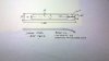
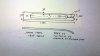
I don't have a schematic, so am not sure of the correct nomenclature of the part, but it is critical to the function of the cylinder latch: It is a complex spring-like piece which lies under the latch/rearsight bar on the top of the frame, retained there by the screw which is visible on the top of the latch body - its function appears to be to serve as a contact/wear surface between the cam on the top of the hammer (which lifts the locking bolt out of engagement with the cylinder notch when the hammer is cocked) and the body of the latch. Its function is critical to the timing of the revolver, and, unfortunately, in my revolver, has been broken, with the critical portion of the piece missing altogether; the result is that the hammer cannot lift the latch out of engagement, so that the cylinder cannot rotate.
I could make one, but without a sound and complete original example to copy, am not enthusiastic about trying to properly proportion and shape the thing by cut-and-try.
SO... does anyone know of a source for an original or reproduction of this part (and what it is properly called?) - Old Fuff? Anyone?
Failing that, does anyone know whether the #2 revolver part is interchangeable on the 1 1/2 - I know the #1 is too small, since I have a working example of that, but do have a friend with a good #2, which I believe I could copy?
I really want to shoot this neat little revolver, since I have access to a good supply of proper ammunition, and it is in such nice shape, but am currently in need of help...

Thanks;
PRD1 - mhb - Mike
 
Apparently not...

at Dixie - at least their on-line catalog doesn't admit to having the part (or any part for early S&W revolvers, except the cylinder latch spring for the #1.
Thanks for the input.

PRD1 - mhb - Mike
 
This may get complicated because during the production of the little 1 1/2 Smith & Wesson made some engineering changes to the cylinder stop. And these were running changes because trashing any useable parts would cause them to get emotionally upset, so anything that could be used... was, without any special notice of serial numbers.

I presume the one you have has the cylinder stop mounted in the topstrap above the cylinder, but it's not impossible that it's under the cylinder, in front of the trigger.

Please post a serial number, which may or may not be helpful. With additional information we can go forward.
 
Howdy

The part you are referring to is called the Cylinder Stop Spring, according to David Chicoine's book Antique Firearms Assembly and Disassembly. And it is very common for it to be broken.

You also should mention that your revolver is one of the very old Tip Up revolvers, rather than the later Top Break revolvers.

Here is a photo of the three different sizes they were made in, from the top; #2, #1 1/2, #1.

ThreeTipUps01_zps4e547eb7.jpg


For what it's worth, I just checked my #2 and # 1 1/2, and I don't think the #2 spring will work in the #1 1/2. The larger gun has a wider spring, although they appear to be fairly close in length. Pin hole placement may vary though.

If you are good though, you could probably make up a new spring, using the #2 spring as an example, varying the dimensions to fit the smaller gun.

You are correct about the function of the part. The spring snugs the cylinder stop down. When the hammer is cocked, the rear of the bump on top of the hammer raises the spring, raising the cylinder stop. When the hammer falls, the wedge shaped front of the bump splits the spring open, so the cylinder stop stays down and engaged. I cannot offer any advice about where to find a new spring, usually collectors buy junkers to cannibalize for parts, and unfortunately this spring is often broken on junkers.

lockworkcocked.jpg


I assume you are aware these revolvers fired 32 Rimfire, not centerfire, ammunition? It has not been made in many years, and you absolutely should not try firing Smokeless powder in these very old guns.
 
Last edited:
Old Fuff and Driftwood:

Sorry for any confusion: I did mention that it is a 2nd issue, and the location, method of attachment and presumed function of the part, which I thought would be sufficient I.D. - the serial number is 76680, and it is nickeled. It is of the same model as Driftwood illustrates - in fact, a virtual twin, so far as condition goes. I don't have a good reference for production dates, but presume, from the known range of serial numbers for the type, that this example dates from 1872 or '73.
I am aware of the ammunition issue, and that it is chambered for .32RF.
I am able to make a new spring, but would very much like to have an original (or good reproduction) to use as an example, because the proportions and precise locations of the 'features' in this complex part are undoubtedly critical to its proper function.
And, of course, if I can buy a proper replacement, I will be spared a heap of aggravation.

Thanks, both, for the responses!

PRD1 - mhb - Mike
 
Howdy Again

You might try signing in over at the Smith and Wesson Forum and see if anybody there has a spring they can sell you.

The SN on that #1 1/2, Second Issue of mine is 890XX and it shipped in January of 1873.

I only mentioned it is a Tip Up because many shooters are not aware of them. When you say #1 1/2, or #2 many assume you are talking about a Top Break.
 
Driftwood...

Thanks again!
I signed-up at the S&W forum, and explained my dilemma - I hope someone can help with the part I need.

PRD1 - mhb - Mike
 
There are two springs in that mechanism. The one screwed to the cylinder stop is not just a spring, it is a critical part of the cylinder stop mechanism. One end, as you note, is screwed to the cylinder stop; the threads are in the spring itself. The other end is split. When the hammer is cocked, the lug at the top of the hammer engages the back of the slot, raising the spring and the cylinder stop. When the hammer falls, the more pointed front of the lug divides the sides of the spring without moving the cylinder stop.

You should be able to make one from spring stock or something like an S&W or a Colt SAA mainspring, cutting it out with a Dremel tool. It needs to be about .022" at the screw hole to have enough thread. Count on spoiling a couple, though, and you will have to re-heat treat when you have one that works.

The second spring is easier, it is simple curved spring and is held in by the middle pin of the three in the top strap. It goes under the rear two pins and curves upward to power the cylinder stop.

Remove the front pin, and check to see if the split spring is there. If it is, see what is broken. Usually it will be one of the sides. If it is gone, I will send dimensions and photos to show what it should look like.

Jim
 
Jim K.:

I've already dis-assembled the cylinder stop from the frame and determined that the cylinder stop spring is in good condition - it is the split spring which is broken and missing its 'working' end. The attachment end is still connected by its screw, but the part has been broken just rearward (toward the grip)of the screw hole, and only part of the remaining spring body was still in place, though the functional portions are gone, leaving only sections of the thin side bars.
I would very much appreciate a good drawing of the part, with dimensions, which will allow me to make the thing without too much cut-and try. Photos and/or a tracing of the part would also be helpful and appreciated. I know basically what it should look like, but, as I said earlier, I'm sure that the precise location, proportions and shapes of the missing sections are critical to the timing and correct function of the revolver. I can determine the thickness of the part at the attachment point, from the remaining piece, but really need the other pertinent dimensions.
Also, if you know what the thread of the retaining screw and corresponding hole is, that would be appreciated, too.
Thank you very much for the response - the information is exactly what I need, and will be useful and appreciated.

PRD1 - mhb - Mike
 
I've often though it would be neat for one of the replica makers to make a S&W Model 1 in .22 short. From my readings, these were a popular gun during the U.S. Civil War not as a fighting gun, but just personal defense off the battlefield.
 
I doubt you will see that. S&W itself has not had good luck doing repros and right now they are running full out to keep up with the demand for current guns. Plus, those guns were quite fragile, and self-destructed rather quickly under even a relatively small amount of shooting, even with black powder. The top hinge is weak, the latch is weak, the cylinder walls are thin. They are not 686's.

Jim
If my NAA mini can shoot hundreds of rounds of CCI .22 LR ammo with no problems, I'm sure a modern S&W Model 1 could be made to do the same as well with all the advances in metallurgy and manufacturing in the past 150+ years.
 
It is amazing what folks think "advances in metallurgy" can achieve. Baby Brownings in .300 Win Mag, blowback pistols in .500 S&W, top breaks in .44 Magnum. Yes, we have seen great strides in metallurgy (and non-metal for that matter), but the the hinge pin of a Model 1 1/2 measures 1/10 inch, not quite what would be wanted for durability over the years.

Besides, who would want one? Right now I see a market of one (1), hardly a massive demand that would induce a factory to invest millions in machines and tooling to satisfy. I suggest not holding one's breath waiting for the new tip-ups.

Jim
 
Hi, PRD1,

I am going to try to attach a drawing of the part. Let's see if it works.

Jim
 

Attachments

  • 02 13 16 001.jpg
    02 13 16 001.jpg
    35.2 KB · Views: 13
Another maybe clearer. Good luck.


Jim
 

Attachments

  • 02 13 16 002.jpg
    02 13 16 002.jpg
    49.9 KB · Views: 19
Jim K.:

Thanks! That is very helpful. Just a few questions:
What is the distance from the forward (screw hole) end of the spring to the beginning of the lenghtwise opening in the spring body?
Are the sidewalls of equal width (presumably .033" at some point ahead of the beginning of the opening), and as it appears, tapered with the reduction of width of the body?
What is the width of the central opening, and is the radius the same at each end?
And, is the spring of equal thickness from end-to-end, or is it tapered in that dimension, too?

Thanks!

PRD1 - mhb - Mike
 
I didn't include the hole position because you said you had that part of the spring. The hole is .07 from the slot to close edge of the hole and the same from the rear end to close edge of the hole in that direction. Note I said edge, not center. The hole to slot distance is not critical, but you will want to leave material at the front that can be removed to get the hole lined up.

The screw looks to be a 4x40 or4x42, but remember there were no standards in those days so what looked right to an S&W tool maker would have been OK.

The "sidewalls" are of uniform thickness end to end. The slot is .123" wide at the rear, .107" at the front. I see I made an error; the slot is rounded at the front, but squared off at the back, likely better to engage the lug on the hammer. (Sorry about that!)

The spring is of equal thickness, end to end.

The slot is needed to fit around the lug in the cylinder stop, and let the sides flex without breaking. The critical part, and which will require careful hand fitting, is the rear, where the hammer lug has to lift it in cocking, then wedge the sides apart when the hammer falls.

Now here is the good part. The slit is nearly invisible; no tool could have cut it. I think the spring was originally un-tapered. I think they made it parallel, then cut the slit, and squeezed the sides together before tempering and drawing; that resulted in the taper.

If I were making that part, I think I would cut the rough outline and drill the hole, then use the hole as a reference to the rest of the work and also to secure the work to the fixture.

The really tricky part will be getting the rear part right, where it interfaces with the hammer lug. That will be a job for pattern makers files and a lot of patience.

Good luck.

Jim

Edited to add a PS. If originality is not a biggie, I suggest you replace the cylinder stop spring with a short coil spring, a piece of ball point pen spring will do. The gun will work a lot better.

JK
 
Last edited:
Jim K.:

Thanks again!
I didn't actually ask about the location of the screw hole, but the central aperture's distance from the end of the piece. Since you gave the length of the aperture, but not the length of either the screw end slotted end, I wasn't sure about the actual measurements of those important features.
Appreciate the additional information about the square end of the slot at the working end - I had wondered about that.
I did know that screw threads used by the gunmakers of that era (and even later) were not standardized, but I have a large selection of bastard taps, etc, and hoped I might have something pretty close - I'll just measure the screw.
Also appreciate the tip about the coil spring.
I'm a persistent cuss, and no stranger to files - I'll let you know how the project turns out!

PRD1 - mhb - Mike
 
I've often though it would be neat for one of the replica makers to make a S&W Model 1 in .22 short. From my readings, these were a popular gun during the U.S. Civil War not as a fighting gun, but just personal defense off the battlefield.

Smith and Wesson changed over from the Tip Up design to the Top Break design around 1869 for a couple of reasons. First of all, the White Patent for bored through chambers, which S&W was licensed to use, was about to expire and S&W were sure all the other revolver makers were chomping at the bit to introduce revolvers with similar bored through chambers. So S&W came up with the first of the Top Break designs, for the big 44 caliber centerfire revolver that eventually became known as the American Model. The Top Break was a much more advanced design than the Tip Up, because S&W felt they needed to upstage the competition they were expecting when the White patent expired. The Top Breaks offered several features that the Tip Ups did not offer, the most important being automatic ejection of spent cartridges as the gun was opened.

The other feature was the strength of the design. Although not as strong as later solid frame Hand Ejectors, the Top Breaks were much stronger than the Tip Ups. S&W never made any Tip Ups in any calibers larger than 32 Rimfire. They experimented with 44 caliber Tip Up, but concluded the design was not strong enough for a large caliber like 44.

And although the Tip Up was a very simple and elegant design, it was very common for the spring in question, to break. Very common. I see old Tip Ups all the time that only have half the spring, the other half having broken and disappeared long ago.

The Top Break was a much stronger and more robust design than the Tip Ups. That is why when S&W got around to making smaller 32 and 38 caliber designs after introducing the big 44s, they were all Top Breaks.

No matter what the metallurgy, a Tip Up design today would still be a weak design and would have very limited appeal other than as a curiosity.
 
Last edited:
Status
Not open for further replies.
Back
Top