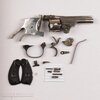
Meriden 'The Aubry' DAO 32

Know a machinist? Pretty easy to take a larger diameter screw of the same thread pitch and turn it down to the diameter you need. You can then cut some flutes in it to turn it into a tap. Should be cheap enough. You should buy a thread checker to use to verify thos threads. Yuo can find them used for cheap on Fleabay.

Other than Jackrabbit, no I don't. Hoping to take a trip down to visit him this weekend.

I did find my thread gauge. But that just checks the outside threads. I have a screw checker for gun screws that Ace hardware sell along with their gun screws. Is that what you mean by thread checker? Something similar to this.

61TNR8Ea8IL._AC_SY879_.jpg

Unfortunately mine doesn't go up to 1/4"
 
I started a long post on how we got the Meriden functional. But it's late and I wasn't doing it justice. So I'll regroup tomorrow and try again. For now, here is a poor video showing function.

https://photos.app.goo.gl/Ayw8aXv3FY1pc3aj6


This is the best I could come up with for a parts list.

Topbreak-32-Nickel_MwAiO_1.jpg
 
Last edited:
Cool project and $75 doesn't buy dinner for two at a nice restaurant.

Will you shoot it when you're done?
 
Will you shoot it when you're done?

Absolutely it'll get shot. Although all of my black powder 32 S&W's eat a 32 lead round ball over a case of 3F. Mild to say the least but accurate at 7 yards so far in my other 32 S&W's.

Evidenced by the sheer number of 32 S&W's sold in the latter part of the nineteenth and early in the twentieth century it was once thought of as a viable self defense round in that same time period. It is pretty anemic. I heard/read someplace the saying regarding the 32 S&W "any vest is a bullet proof vest". There's also the story, (we used to call them Urban Legends) about a man in South America who unloaded one of these tlp breaks at his wifes head at close range and she walked to the ambulance.
 
Cool project and $75 doesn't buy dinner for two at a nice restaurant.

I think I saw a nice hammered version of a Meriden sell for $130. So this was purely an academic exercise to see if I could do it.

Pre-antibiotic, any penetrating wound was dangerous.
Killing power, psychological stopping power.

Understood. I suppose that was the theory for all those 22 short suicide specials. There were millions of those sold too.
 
So I'll regroup tomorrow and try again.

Detailed posts take so much time to do correctly. I’d give anything to have @Driftwood Johnson ’s skills at putting together posts like his. They are so succinct and well written.

Needless to say I think I’ll update the recent work in several posts to follow. Here is how they will be grouped:

- Replacing the star extractor

- Fabricating the trigger return spring

- Installing the firing pin/bushing/spring

- Finnish issues.

I’ll try to start them tonight.
 
The picture above was from a sale ad from a website called 'Everygunpart' that sells parts kits. they destroy firearms for municipalities and sell the remaining parts as parts kits. I used it because as a solid frame (no side plate) I couldn't tell what the parts 'inside' the gun looked like. And there are no diagrams of any Meriden firearms that I can find.

Sorry for the confusion.

The pic above has me puzzled... the grip frame appears to have been cut short.
 
Last edited:
The folks at Cornell Publications who sell old catalog reprints frequently point out in their newsletter and correspondence that schematics with parts shown in place in sectional or ghost views is a fairly recent thing. Parts just laid out like that Everygunpart ad were the standard in those guns' day.
 
Extractor Star

I mentioned in an earlier post, Numrich had a cylinder with extractor for sale and I bought it. It was for a Meriden small frame revolver. It should fit, shouldn't it. I mean this is certainly a small framed revolver. Well, no. Maybe there was an engineering change or maybe the hammered version used a different method to retain the cylinder but the one Numric sent was threaded on the inside of the center pin hole and my cylinder was threaded on the outside of the cylnder pin. it would not mount to my center pin. But it had the extractor and like most (if not all) top break extractors, it was on a two piece extractor rod. So the cylinder won't fit, but maybe the half of the extractor rod that contains the extractor star would? And it did. It took quite a bit of fitting to make it work. Even though the 5 sided extractor rod was the same shape and basic size, it had to be filed to move smoothly through the middle of my cylinder and allow the extractor star to sit flush inside the recess in the cylinder.

The new extractor rod/star was tapered on the bottom side of the star and prevented the star from moving into the recess in the cylinder.
cylinder 2.jpg
And once the extractor rod was fitted, the 'ears' of the star had to be fitted into their recess' in the cylinder.
cylinder 1.jpg

File, install, test, repeat. I still have some fitting to do as you can see in the photo directly above, one of the legs of the extractor star sits proud of the cylinder and that round will fall out of the extractor when the revolver is opened. There is also one cylinder that won't easily accept a sized empty case. Not sure what that issue is. But it doesn't look damaged and I have cleaned the chambers vigorously. That will be for another day.

Sometimes the cylinder comes loose from its retainer when the revolver is opened for extraction. For those not familiar with how the cylinders are held in place on most top breaks, most use a very course thread on the cylinder that ends that mates with a similar thread on the frame. In this case instead of the frame being threaded on this revolver, the frame comes to a point and the thread on the cylinder 'threads' onto that point. Once it is threaded onto the frame far enough the thread on the cylinder ends and allows the cylinder to rotate freely as the threads are no longer in contact with the frame. It can move slightly front to back as well as rotate. The rotation direction of the cylinder is in the 'tightening' direction for retaining the cylinder. It is kinda hard to explain in words. So here is a short video of the retaining of the cylinder.

https://photos.app.goo.gl/VFTonUcZ3sdguYsv6

And a picture of the cylinder retained on the center pin
cyl3.jpg

This is the thread on the cylinder. It is hard to see as there are only 1 1/2 total threads. You can see the start of the threads on the top closes to the cylinder. just to the right of the spring closest to the cylinder.
cyl2.jpg

In this photo the frame isn't threaded but comes to a point that the thread on the cylinder 'threads' onto.

cyl5.jpg

So I have a little bit of work to do on the cylinder. But basically it is now functional. Well, it will be fully functional when I'm done. We'll call this 'tuning' and move on.
 
Fabricating the trigger return spring

You would think that a simple spring would be easy to make. Well, it isn't so easy if you don't have a broken one to replicate. I first tried to make a V spring like the S&W or even the H&A's use. But I was unsuccessful. Then I found the picture of the parts kit in one of the above posts and was able to see that it was a leaf spring. So I tried to make that out of an old mainspring I had but again, I was unsuccessful. Wolff Springs sells a package of trigger return springs made for H&R and other top break revolvers. So I ordered them. 4 copies of 3 different sized trigger return springs.

a.jpg

b.jpg

I picked the smallest/thinnest spring to make the trigger return spring. The spring had to be 'narrowed' to fit in the slot in the frame. I used the factory drilled hole that had to be reamed to fit the screw and fitted the length. Using the factory drilled hole was a tactical error becuase when I fitted the length I was taking off part of the 'curve' of the spring. One has to get the length just right to hit the exact spot on the trigger to return the trigger. Too long and the spring would bind on the trigger. Too short and it wouldn't reach the exact point on the trigger and return the trigger. Testing of the new spring showed it was just strong enough to return the trigger without the cylinder installed. It feal very weak. Once the cylinder was installed the drag from friction on the trigger/hand was enough to make the trigger return spring unreliable for returning the trigger. It was just too weak. So if the smallest/thinnest spring was too weak to reliably return the trigger, I used the biggest/thickest spring in the Wolff kit and made another. It was a little bit easier now that I had one that was the right shape to basically copy. It still felt weak but was strong enough to over come the friction/drag with the cylinder installed. Unfortunately when the double action sear was installed the spring was again too weak to reliably return the trigger. The double action sear is another piece loosely attached to the trigger guard/trigger and is just a 'bugger' to install. Now I was sure none of the springs in the Wolff kit would work. On a lark I put both the orignal spring I had made and the second spring in and guess what? It worked. The trigger return now felt like it should and it was plenty of force to overcome the drag from the cylinder/trigger/hand/double action sear.

Here is a picture of the second spring I made. Notice there are two holes in it. The first spring I made looked just like it but used the factory hole.

d.jpg

Now, drilling a hole in hardened spring steel isn't easy. I suspect the correct way to do it would be to anneal the spring, drill the hole and re-harden and temper. Although I probably could have figured it out, I wasn't comfortable with that process. So a slow drill, sharp tungsten/carbide drill bit and tons of cutting oil did the trick.

But I had to hold the spring on the drill press. Keep in mind that I have a Harbour Freight drill press that I don't trust to hold a precision alignment. Getting the drill table perpendicular to the drill bit is an eyeball operation. That in and of itself took quite a while. But how to hold this tiny spring while I drill on it for minutes at a time? I had to make a 'jig' to hold it. Two pieces of brass sheet. One carved out to receive the spring and another full sheet underneath the first sheet to form a bottom to hold the spring in place from the bottom. It work fine:

h.jpg

g.jpg

Now, unless I decide to re-nickel this revolver (and I might as a practice piece), the trigger guard, return spring, and double action sear will never come out of this revolver as long as I own it. It takes 3 hands and holding your tongue in just the right spot to put them all together at the same time. And a slave pin is necessary. Here are the parts/pieces involved

Notice on the right side the double action sear is inside a recess in the trigger guard. The double action sear is held in place by a pin through the frame, then through the trigger guard, then through the double action sear. In order to keep the double action sear in place during assembly I filled the recess the sear resides in with grease to generally hold it in place, placed the sear in the trigger guard, made a slave pin that was just narrower than the trigger guard all to hold the sear in place during installation. Installation was to insert the trigger guard screw, place the trigger return spring on the screw, start the screw just barely into the trigger guard then finagle the trigger guard into place then drive the full length trigger guard retaining pin through the frame, through the trigger guard and then the double action sear and out the other side of the frame. Needless to say that took more than one try to accomplish.
e.jpg

And assembled

Trigger Guard Screw.jpg

I have not had the trigger or the hammer out of this revolver. As a solid frame I can't tell how difficult it would be to reinstall them. Plus, there is a piece of the frame that looks like a filler for a slot to install/remove the hammer. But there are no retaining pins to hold it in place. It show up better in one of the auction pictures before it was cleaned of rust.

m5.jpg
 
Installing Firing Pin, nut/bushing, spring

In a previous post I noted that the firing pin bushing was actually what Numrich called a nut. The threads are on the outside, I would have called it a bolt or screw. But no matter what you call it, unlike a S&W, this bushing threads into place instead of being a friction fit. I measure it as 1/4-40 TPI and the threads inside the revolver were buggered. Not terribly bad, but enough that I could only screw the bushing in about 3/4 of the way. Someone suggested it could be a #16 screw and I suspect that is what it is. A screw size that is long obsolete. Searches for a 1/4-40 tap or even a screw have been fruitless. Pictures for orientation:

Stripped threads inside the revolver
Capture.JPG


Firing Pin Bushing/nut
Firing Pin Nut.JPG

firing pin nut 2.JPG

Firing Pin
Firing Pin.JPG

Firing Pin Spring
Firing Pin Spring.JPG

I ordered another bushing/nut from Numrich and it is on the way. I used the bushing I had as a tap to clean up as many threads as I could but I still couldn't screw the bushing in far enough. Because I had another on the way I thinned the bushing to very close to flush with the recoil shield and filed the top to get it to flush. I took out about 1/4 of the thickness of the bushing.

Now to install the firing pin and spring. Unfortunately what Numrich sent wasn't the right firing pin. It was much too long and thick and stuck out 3/8 of an inch when installed. I had to thin the pin part a bit and shorten the length of the pin. I removed the length of the pin from the hammer side to five the firing pin as much 'travel' as possible.

It seems to work fine. At least it does without firing it. I'll re-address this when the second bushing comes in and I can find something to rethread the revolver. If it keeps on working, it may never get changed. Here is a picture of it all installed.

Bushing flat.jpg
 
Finish Issues

Not sure where to start on this topic. It was ugly, rusted. But my wife likes the gun and thinks the fact that it was a minor player in the market might make it more valuble. I have no such misconceptions.

I've mentioned this in other posts on other guns, but Aluminum Foil is great for cleaning up nickeled guns. It is softer than both the nickel and the underlying steel. So it doesn't scratch anything but is real good about getting the black powder out of all of the nook and crannies.

As taboo as it is, I did take a wire brush to remove the rust from the sides of the frames. But in this case I used a copper brush rotating slowly on my roto tool.

Later this summer I'm planning to start with one of the nickel plating kits from Caswells. And this might be a candidate for a re-nickel project. But that is long in the future. Before and after pictures.

Before
Before Left.JPG

After
20230522_072524.jpg

Before
m5.jpg

After
20230522_072750.jpg

20230522_072555.jpg

20230522_072718.jpg

20230522_072723.jpg
 
Looks like a fun project.

The gun shop I part timed at back in the late 1990's had multiple 5 gallon buckets full of broken top break revolvers. The owner of the shop was a gunsmith and bought the buckets for next to nothing.

I have a top break 32 in my gun safe. My "wife" bought it for $20 while visiting a relative living in an apartment complex. It came from the relative's neighbor. I'll pull it out and snap a pic of it.
 
Not at all surprising that the extractor star needed fitting. The star of my US Revolver, a five shot .32, will only fit one way, not five.

If you look at the above picture of the star retracted , you can see a punch mark on the leg/ear at thd 11 o'clock position. This would align with the assembly number on its original cylinder. Some revolvers have a punch mark on the cylinder to index the fitted position of the star. In this case I found the position that needed the least amount of fitting and made a new mark on the star.
 
In post 36 I pointed out how the cylinder is retained and that at times my cylinder would come loose while opening/ejecting cases. To fix that I gently displaced some steel where it comes to a point on the frame to provide a bit more bite for the threads on the cylinder to grip onto. Reality is the threads on the cylinder were worn in one spot. But I couldn't figure out a way to 'grow the threads.

It only took a few taps and man is this steel soft. But it now retains the cylinder all the time. Here is where I displaced the steel. I used an 1/8" punch and the small hammer that came with the punch set.

20230524_211320.jpg

And here is the picture of the cylinder being retainedbfrom post 36

cyl3.jpg
 
Last night I addressed the cylinder. Two of the 'legs/ears', (not sure what to call them) on the extractor star didn't sit flar/flush in their recess in the cylinder. Although the cylinder would rotate/function properly, i could feel when those cases would pass in front of the firing pin bushing. So they really needed to be addressed.

Here's what we started with
cylinder 1.jpg

I tried to gently bend the extractor star and then the two ears. But the extractor/star seems somewhat delicate. The 'ears' themselves appear to be made from somewhat hardened steel and feel like they'd snap if bent too hard. I ended filing the protruding metal out of the way. All 5 cases now sit flush. Although the extractor star now fits into the cylinder well, this extractor in this cylinder doesnt grip the empty cases well. I'll have to turn the revolver upside down to assure cases won't get trapped under the extractor star. I'm pretty sure that is the way extraction was supposed to be done on any top break.

IMG_5749.jpg

The one cylinder that wouldn't accept a sized case had 2 small burrs. A little judicious file work and that problem is cleared.
 
In a previous post I surmised that the design of this revolver had the cylinder free spinning. I reviewed the parts of the trigger and confirmed that the cylinder stop was formed as a part of the trigger and can only rise when the trigger is pulled back. Notice the trigger/cylinder stop in the picture of the parts

Screenshot_20230525-200330_Chrome.jpg

So the cylinder free spin was part of the design. As late as this revolver was designed I would have thought it wouldn't free spin.
 
The primary design criterion was "make it work with the smallest parts count possible."

True. I’m sure this one was targeted for the same market as the IJ’s, H&R’s, and H&A’s of the day. 1/3 to 1/2 the selling price of a similar S&W model. But even those other low cost lines refined their double action revolvers to lock up when at rest by the time this one was designed. Fewer parts/lower costs to compete but I would have thought free wheeling cylinder was considered inferior compared to those other brands. If you think of it, once fired the free wheel operation could end up with a fired case under the hammer after the first shot.
 
I really need to get some help taking videos. One handed doesn't really work well.

The functional work is done and the revolver is now fully functional. I received another firing pin bushing yesterday, but I'm in the same boat as I was before. I don't have access to a #16-40 bottom tap or even a screw i could make into one. i'll keep working on that one, but the modified bushing seems to work just fine. Here is a funciton test video:

https://photos.app.goo.gl/SzTof43XfR1upQNN9

It does eject shells with the new extractor star. But you better have the cylinder pointed slightly downward or you'll be picking empties from under the star.

Here is a prime example of cerebral flatulence. I tried to fit the new bushing in today just to see if I managed to get enough threads using the older bushing as a tap. In that operation I did mange to 'bugger' some of the upper threads on the bushing and I thought maybe I gut enough. Well, while taking the firing pin out it hit the table. No mare that 6" above and I was in the middle of the table. But that firing pin vanished like a fart in the wind. Fortunately Numrich has another one. BTW - I didn't get enough threads to use a full sized bushing. So I'm still lookng for a #16-40 or even a 1/4-40.
 
Back
Top