MoreIsLess
Member
What kind of pin punches do I need for knocking the pins outs of my M&P CORE in order to install the Apex DCAEK, flat or roll pin punches? Brass or steel?
")


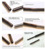
Replacing the trigger spring is quite easy. The Apex kit comes with a polymer slave pin. This one here just happens to be steel. The tip is assemble the the trigger-trigger bar sub-assembly
outside of the frame ! as you can manipulate the spring loop about the slave pin much easier.stall the sub-assembly and then simply displace the slave pin with the Trigger Headed Pin. No commotion necessary.


Ans. # 1. You use the drill bit to create a space in the yellow slave pin, then shaft of the drill bit is secured with Gorilla glue.
Ans. #2. IF you use the sub-assembly method then the first slave pin is too long, as both ends are now sticking out of the locking block. The second slave pin is the exact width of the locking block so you
can then drop the sub-assembly into the frame, then push slave pin #2 out with the Trigger Headed Pin. Done.