Pack/Bicycle Rifle Project Options

Status
Not open for further replies.
I spent about an hour today thinking through the options...

1) Little Badger; I think there's both too many features I don't care for that are intrinsic to the design, and not enough 'cool' to make accepting them worth my while (picky, I know, but that's me)

2) NAA revolver; strong front-runner at the moment, though with some very significant downsides. Muzzle blast will be terrible compared to any sealed breech design, and when you can find them, people seem to be very proud ($) of these revolvers.

3) Modification; I just don't think there are any sufficiently skeletal 'old' guns around at my price point. I'm pretty sure their being skeletal is a large reason there aren't many Game Getters/etc. still existing ;)

4) New design; after sketching out ideas for about an hour, I think this is much more doable than I'd thought. A tiny rolling block from sheet metal & a few welds would be a breeze to build (probably on par with a Jaco), and a Peabody-ish design I came up with looks very promising also. One idea that occurred to me, which I need to explore further (namely feeding) was to borrow from the Spencer, and feed from a narrow tube forming the butt like the original (except this one would fold up while retaining the rounds like a folding AR buffer tube). Faster follow-ups, zero weight penalty :cool:

The various 'elderly school' black powder actions are very compact, and also tended to be very easy to make with hand tools (and were composed of few parts). Sounds perfect for my needs, here, but of course the catch is actually completing the thing. I know some folks with either water jets or laser cutters, that would greatly simplify construction, leaving me to only bother with fitment (which is still about 90% of the job). But for the several designs I looked at, I think you'd have a couple side plates cut from 1/8" plate, the internal form blocks & bolt from 1/4" or 3/8" key stock, cross/pivot pins from cold roll rod (ductility is a good thing in shear), and some music wire springs.

As far as butt-feeding actions, there's the Spencer, Evans, and elusive Meigs, that I'm aware of. I believe all are variants of the Spencer rolling/sliding block mechanism. Any others not of the Spencer/Rolling Block variety?

TCB
 
What about a Chiappa Double Badger? I picked one up 22lr/.410 and its become my favorite woods gun. Squirrel, rabbits or birds with either the 22 or .410 with shot. Larger varmints can be handled with a .410 slug/buckshot. Its really short and handy, it can also be folded much like the single shot version. 22 is plenty accurate for my ability with irons and the shotgun patterns well
 
I have a T/C Hotshot Youth rifle (.22lr) that I added a buttstock pad to, in order to make the LOP correct for an adult. I had a smith shorten the barrel from 19" to 16". It has a peep rear sight, and weighs less than 2.25 lbs!

It is my backpacking / kayak rifle.

I had a Chiappa L'il Badger in .22 mag that I made a lot of improvements to, but in the end, the quality still wasn't there so I sold it. Yeah, AR7s are jammomatics.

In the end, that pack rifle looks like the shiz-nizzle in this genre - I'd take one. Would be slightly more interesting in .22 mag or even perhaps .38 special, but .22lr is great too of course.

But what does the tube under the barrel do?
 
Last edited:
I believe the packrifle is a semi-auto, and that tube would be the magazine.

How's this for a design idea (not quite at the pictures stage, but I can 'see' the design, now);
-Inverted falling block (block rises out the top partially to open the breech)
-Lever action (45deg pivot of trigger guard)
-Internal shrouded hammer fired, cock on opening --so some attention would need to be paid to safely discharge the hammer before stowing the gun)
-Pivoting ejector, like the old Remington Rolling Block 1902's
-Tubular magazine in the butt, which slides out and stows in a socket in the receiver below the barrel (like a typical tube magazine), possibly on a pivot like an SKS bayonet (it loads from the front, too)
-Flat sheet metal construction (side plates & profiles, screwed together over the barrel) of all parts but the bolt
-Bolt/block is composed of easily milled or filed features (all cuts are slots; no pockets)
-6 major moving parts (block, feeder arm, trigger, hammer, ejector, lever)
-2 pivot pins (block, feeder arm, trigger; hammer, ejector, lever)
-3 wire springs (lever, feeder arm; block, trigger; hammer, ejector)
-Spring loaded ejection and feeding (so lever speed is not necessary for proper function)
-Dry fire safe (hammer smacks into the ejector across a large surface if no cartridge is present)
-Highly dropped comb (about 45deg, which is a fortunate coincidence of the current design that works well in this particular situation) which allows for a semi pistol grip, and better sight/eye alignment from a very short stock
-Trigger in line with the hammer (by which I mean both are immediately below the bore axis, so the overall action height is about the same as the trigger guard's
-It's not done, but I think the action will be about the size of a Matchbox car

The one major drawback to the design at present is that it ejects straight back and upward slightly :)eek:) but that's what shell deflectors are for :p

TCB
 
I'm interested in all these ideas. Some are good and others better. I'm encouraged to try a few things myself as I like to do some gravel grinding myself. A packable gun and fishing hear are good additions to an adventure.
 
For a rimfire solution the idea of flat plates that get stacked to form the receiver is certainly doable. There was the old Remington Improved Model 6 which used this same idea. But instead of stacking around the barrel the barrel had a lug and retention screw that sockets down into a space in the middle layers.

Instead of screwing this action together I'd go with some countersinking of the outer plates and a light press fit on the cross pins. The pins would then be peened/riveted over so they mushroom out and fill the counter sink reliefs. This peening also compresses the parallel portion of the pins and firmly holds the parts all together. But even so this layering style construction isn't good for side loads. Which is why I suggest you skip the threading or wrap around idea for retaining the barrel's chambering stub.

I'd also suggest that you want to use something like O-1 flat ground stock for the laminated receiver and have the parts all heat treated to a spring like temper to avoid the recoil cold shaping the parts over the years of use. Commercial heat treaters can do batches of parts for pretty reasonable costs. I had a batch of drill rod pins heat treated a bunch of years back for the minimum $20 charge. I'm sure that's more like $40 these days. But it would be well worth it for the toughness and higher yield point it would provide for the metal.

Done in this method I think it would be possible to make a pretty nice rolling block setup or even a falling block rifle.

For anything other than .22LR I'd want to include some press fit "dowel pins" as well as the softer rivet pins. The rivet pins to hold the plate stack together and the hardened dowel pins to provide the shear resistance to avoid the center layers shifting by bending the rivet pins.

Note that to do this job well we NEED press fits for the hardened dowel pins and riveted permanent lamination rivets. Any sort of "slip fit" and screwed assemby that allows the stack to be broken down means enough clearance in the fit of the holes that we can't obtain solid positional locking of the parts. So no cheating! :D
 
"Instead of screwing this action together I'd go with some countersinking of the outer plates and a light press fit on the cross pins. The pins would then be peened/riveted over so they mushroom out and fill the counter sink reliefs. This peening also compresses the parallel portion of the pins and firmly holds the parts all together. But even so this layering style construction isn't good for side loads. Which is why I suggest you skip the threading or wrap around idea for retaining the barrel's chambering stub."
Riveting sounds good, but you can't get near the clamping force as with threaded fasteners. If good, shanked (as opposed to full thread) screws are used, with good, transition fit holes, you get an extremely good joint (that's how aircraft Hi Loks work, which are significantly stronger than rivets, especially over a grip as long as a receiver width)

"I'd also suggest that you want to use something like O-1 flat ground stock for the laminated receiver and have the parts all heat treated to a spring like temper to avoid the recoil cold shaping the parts over the years of use."
"Years of use." Ha! :D Got some high expectations, there, dontcha? :p If this thing doesn't tear up after an hour of shooting, I'll be ecstatic, and assume (probably rightfully) that it'll be good forevermore. I had planned on using 4130 for all the bearing surfaces, simply because some plug welding will be needed to hold certain critical areas like the lugs together. A true 'side plate build' would machine the lugs from the side plates, but I'd prefer to avoid that if possible, and I also think that much tech is unneeded for the lowly 22LR (my math still needs to be done to verify these assumptions, obviously). Case-hardened mild steel would be another good option, as history has shown (alloy steel tends to have terrible corrosion resistance). In any case, I think I can get this thing small enough that it can be easily treated with a torch and quench bucket, without meaningful distortion (obviously you'd leave some important pivot holes undersized then ream them to finish during fitting)

Anyhow, here's the concept art I have, so far; I still need to model the little lever that releases/pushes rounds from the magazine, and acts as a shell deflector. And, obviously, the receiver ;). Animations to follow, hopefully.

TCB
 

Attachments

  • Action Concept.png
    Action Concept.png
    90.1 KB · Views: 19
Here's the anorexic beauty in all its glory (so far). I actually managed to figure out a way (I think) to simplify what I'd described earlier; instead of a shell pusher, the rounds simply squirt out of the mag tube close enough to the chamber that the extractor blade can get them the rest of the way home as it returns forward. The ejecting cases will either glance off the half-cocked hammer, or the nose of the next round sticking out of the mag tube. The mag looks like it will hold 5-6 extra rounds. Barrel is 16", OAL is 26" from tip of stock to muzzle, and the trigger guard is 1" tall. Modeled weight is currently 1.5lbs :what:

The receiver is transparent for clarity, so its hard to examine its construction; There is a single large sheet metal U opening downward which wraps over the barrel in a narrow band. The barrel has a raised lip that contacts the rear of this band, and also has a notch on its underside that keys into a "trunnion" block situated at the front of the receiver below the barrel (pinned/welded to both). This gives two large contact points for the barrel to thrust against, and one to keep the barrel from sliding back; should be plenty for 22's modest barrel friction (I'm gunning for 22LR at this time). There is a second smaller block at the rear, drilled to accept the mag tube. The bolt locking lugs are actually fully visible through the sides of the receiver (load path goes around/under them) to keep overall thickness down, and the recesses they mate to are flat plates covering the entire inside faces of the receiver except for the (wider) trigger --lots of room to put in cross pins or penetrate welds.

Trigger should be gritty, but fairly short and light (lots of contact/sliding surfaces, but engages a sear bent at the tip of the hammer, with a sear located closer to the trigger pivot than the trigger)

Hopefully I'll have a chance to look into the motion simulation systems tomorrow, so I can get a better demonstration of the operation up :cool:

TCB
 

Attachments

  • Layout Concept.png
    Layout Concept.png
    29.9 KB · Views: 28
The one major drawback to the design at present is that it ejects straight back and upward slightly :)eek:) but that's what shell deflectors are for :p

TCB

Hopefully I'll have a chance to look into the motion simulation systems tomorrow, so I can get a better demonstration of the operation up :cool:

TCB

You must have some CAD/CAM experience and software. So far I'm impressed. :cool:

I'm not quite seeing how the empties will clear the breech block, but I'm sure your animation will show that.
 
I would not underestimate the recoil hammering that we can get from a .22LR. The rear webs of the block look a lot too thin to my eyes with this in mind.

Also I'm not sure how you're going to get a good control over the head spacing of the chambered round with the relief needed for the block to pivot up from the barrel. This issue is why the Martini action has a high mounted pivot for the drop block and why the drop down rotating block in the Stevens Favourite is also shaped like it is. These actions locate the pivot so that the face of the block moves back as it arcs away and closes in as it arcs into lock. Having the pivot located directly in line with the bore means that you need some roundness to the face of the block which is going to affect the case head support.
 
Cycle%201%20Fast_zpsfdwdbbwx.gif

Good eye, BCRider;
The forks extending back from the bolt don't actually carry any load (well, unless something really bad has already happened :D), but instead the bar at the front of it. Basically a falling block that rides in a circular recess ('precessing' block) in the receiver. The lugs are 3/8" tall, each with 1/8" engagement --plenty of meat.

"Also I'm not sure how you're going to get a good control over the head spacing of the chambered round with the relief needed for the block to pivot up from the barrel"
Yeah, it's a design compromise. But as small as all the parts are here, it's like .002". Again, talking 22LR, here, not magnum ;). One solution I thought of would be to have the hammer strike be across the enter bottom 1/4 of the case rim; it's mass/spring could be made to support it enough, and it would cock back out of the way when the bolt needs to lift (I'm still not convinced it will be an issue, here)

I'm much more concerned with the U-shaped load path from the receiver recess, around the notch for the block, then back up to the barrel connection, than I am about nearly anything else at this point. I'll be doing stress calculations before I start cutting metal as a sanity check ;), but hopefully I won't need to add another layer of metal to bridge the gap

TCB
 
Or the other option is to simply let the casing head form back onto the rounded face. I seriously don't think it'll rupture.

Now that I see the animation I see what you're saying about the block being supported by the rear portion.

Your animation has a few flaws though. The ejector is shown returning into position AFTER the new round is chambered. I'm thinking that it needs some way of returning or being pushed to return by the fresh round.

The other thing I'm seeing is that the magazine catch is driven by the lever. But there's nothing to catch the round behind the one being chambered when the lever is cycled forward. With only the one rim catch in the magazine it would be free to double feed or even shoot out the whole lot. It needs a second lip or some other method to control and limit the feed to one round only.

Or is this intended to catch the new round on the ejector? And at that point the lever begins to come back which lets the rim catch in the magazine hold back the next round while at the same time the nose of that captured round keeps the chambering round pressed against the ejector?

If I sussed this out right then I think you're onto a bit of brilliance here. If you can make this work you'll really have something. And a design which I suspect could be sold to some outfit to turn it into at least a small series production.

The first step would/should be to make up a barrel in a block receiver that copies your hinged breech block and test fire some rounds to see if the rounded face on the lower edge results in a lockup at all.

Ya know.... if the hinge pin for the rotating block and trigger could be located at or even a hair below the lower edge of the chamber the hinged block's face could be straight up and down and flat. And when it lifts it would be hinged in such a way that it would lift back a little off the case head as it rises. Much like the falling "L" block in a Stevens Favourite hinges down and back by having the hinge point located below the barrel.

I'm also wondering what raises the block? Or is chambering a fresh round a two step process that starts with pivoting the block back and up and then cycling the trigger guard/lever? If so then what locks the hinged block in place? Or are you relying on the fact that the block is inline with the pressure?
 
Awesome feedback, BCrider!

"Or the other option is to simply let the casing head form back onto the rounded face. I seriously don't think it'll rupture."
Seeing how poorly supported the chamber is in my blowback semi (Baikal MP161K) shooting hot ammo, where the rim blows out into a near constant 45deg taper, I think the 22LR case can handle a little deformation without kaboom. In a higher power or centerfire gun, I think the problem would be more due to the relative rigidity of the cases and how they are glued to the chamber under pressure, which would put great stress on them where the case wall starts (truly poor headspace condition). The 22LR case is so thin and low pressure, the metal can more freely shift around without tearing --that's my theory, anyway.

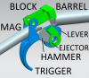
"Your animation has a few flaws though. The ejector is shown returning into position AFTER the new round is chambered. I'm thinking that it needs some way of returning or being pushed to return by the fresh round."
This is totally me being a lazy animator. It is incredibly tedious to make an animated GIF frame by frame; you have to create copies of every part at every position, then hide all the other copies not needed for each screenshot. The ejector is driven mechanically forward by a pin in the lever (only on the return stroke), but is on a slotted pivot hole so it can slide up and down enough to slip over the case rim when the block drops down behind the fully-chambered case(onto the tip of the extractor). In reality, this would occur in the last little bit of lever motion, which I did not bother to animate (which is why the lever appears to reach forward before the extractor slips over :eek:). I may re-animate the last couple slides to reflect the reality, if I feel like it.

"The other thing I'm seeing is that the magazine catch is driven by the lever. But there's nothing to catch the round behind the one being chambered when the lever is cycled forward. With only the one rim catch in the magazine it would be free to double feed or even shoot out the whole lot. It needs a second lip or some other method to control and limit the feed to one round only."
The magazine catch actually does a little two-part motion (the spring seat shown is for a weak wire spring that coils around the mag tube). The first part, it pivots near the spring seat, and the escapement catch at the rear/tail moves inward to catch the rim of the next shell (I modeled it wrong, though; it needs to be positioned just after the next rim, not before. In the current shape, the new round would only feed .02" and then stop :p), and once the escapement catch has contacted the shell the tip of the forward catch will lift out of the way of the front case's rim; allowing the stack to move a little less than a full cartridge length. Once the catch lever is released on the return stroke, the stack will advance the rest of the way.

"Or is this intended to catch the new round on the ejector? And at that point the lever begins to come back which lets the rim catch in the magazine hold back the next round while at the same time the nose of that captured round keeps the chambering round pressed against the ejector?"
I thought briefly about this, but not much. I want to ensure the catch holds the rounds outside the gun, so it can be stowed while loaded ('bout time someone made a front-loading tube mag --talk about fast reloads!). But let's see; if the extractor was a 'notch' instead of a blade, which engaged the rim, it would both push and pull the cartridge. You'd need some hammer relief to support the material added (so the ejector isn't supporting the case itself), but that's not a very big deal. So the new round would squirt out of the mag, come to rest against the ejector, then be dragged forward the rest of the way on the return stroke. That does sound like a pretty slick little system, depending on how 'slippery' those 22LR rims, are. I was more worried that the gyrations of the round slipping into the bore would cause it to 'fishtail' away from anything that could grab the rim, so I opted for a simple push system; but since I've had to add the sliding-axis element (it slides both ways, so the extractor has more "reach" when it comes to feeding the new round in), the true controlled feed extractor you've described might be possible, too.

"The first step would/should be to make up a barrel in a block receiver that copies your hinged breech block and test fire some rounds to see if the rounded face on the lower edge results in a lockup at all."
The block is rounded, so if the arc is correct there should be no reason it couldn't slide along the deformed case head. I had intended to do the test you described, if only because the true single-shot portion of the design would be completed way before the likely-to-be-obnoxious-if-not-non-functional repeating action. I'm an impatient man :D

"Ya know.... if the hinge pin for the rotating block and trigger could be located at or even a hair below the lower edge of the chamber the hinged block's face could be straight up and down and flat. And when it lifts it would be hinged in such a way that it would lift back a little off the case head as it rises. Much like the falling "L" block in a Stevens Favourite hinges down and back by having the hinge point located below the barrel."
Yes, at this point I could move the breech/trigger pivot down without as much impact on function as I'd expected it to cause, initially (it's hard to visualize how much 'flex' a design can accommodate until it is completed). In fact, dropping the lever/pivot about a 1/4" and raising the bolt pivot the same would allow the block to drop down like a proper falling block, without hitting anything.

The reason I'd rather not drop the rear pivot is because I'd have to drop the bolt forks. The mag tube is the same width as the forks, so they would interfere unless I cut the mag tube back quite a bit or cut reliefs in its sides. Raising the rear pivot and dropping the lever would have the beneficial opposite effect, but would make the action larger --I'm not sure it'd be worth growing the action above the top of the barrel, but it'd be kind of funny to use the bolt forks as the rear sight :D. One super-cool side effect would be that the hammer would hold the bolt in line with the barrel like a rolling block, on such a setup. If the pivot is below, there will be significant upward force on the block during firing that will have to be contained, somehow.

"I'm also wondering what raises the block? Or is chambering a fresh round a two step process that starts with pivoting the block back and up and then cycling the trigger guard/lever? If so then what locks the hinged block in place? Or are you relying on the fact that the block is inline with the pressure? "
It's not modeled yet, but I have two pretty simple solutions. The most simple is to have one of the forks hang down lower, and come into cammed contact with the lever, rising fully to eject at the 1/2 stroke point (if I wanted to be fancy, the fork would hang down low enough to form a cam slot for a pin on alongside the lever, but it will only be a ramped surface on this design). The other solution is for a spring between the lever and block to be tensioned when the lever is rotated; like a pushrod, but with 'give' so they don't truly need to move in unison. In both cases, the block is dropped back down by a simple return spring (the trigger return spring) once everything is back in battery and out of the way. I suppose the 'forward assist' for sticky rounds would be slapping the top of the action to get the block down :p. Being in line with the bore (or more likely, .01" or so above it) there should be no load acting in the upward direction on the block under pressure.

1) Trigger pulled, hammer drops
2) Lever pulled, drives up block, begins cocking hammer spring against ejector
3) ~1/2-3/4 lever draw, block rises fully, allowing ejector to freely eject spent case (can't make ejection/feeding too close or the cases will collide when levered rapidly)
4) Lever continues fully, actuating the shell release to advance one cartridge, and catching the hammer on the trigger sear
5) Lever reverses, driving the ejector forward against the case rim and hammer spring
6) Lever continues until the ejector fully chambers the case, allowing the block to fall onto the ejector blade
7) Blade is driven downward, and slips over the case head as the lever comes to rest

At this point, the ejector is tensioned, and pulling the case rim to the rear with the force of the hammer spring (which means the lever will not stay closed with an empty chamber until the hammer is discharged). It has no momentum, so I am not worried about ignition, but I do wonder if this effect could damage the case rim. At any rate, the gun would not be left cocked for very long.

I suppose I could add a feature to the block to 'hold' the ejector in place when no cartridge is present, which would allow for proper dry fire, but that's a fairly low priority (esp. when holding the lever back will still tension the hammer spring). If marketing, I'd call it a 'dry fire preventer' and claim it prevents damage (even though the ejector is the 'anvil' for the hammer, and will be both replaceable and very hard ;))

"If I sussed this out right then I think you're onto a bit of brilliance here. If you can make this work you'll really have something. And a design which I suspect could be sold to some outfit to turn it into at least a small series production."
That'd be fun and all, but there're a few reasons I'm posting this online, as opposed to pretending like I have some great secret that needs guarding. 0) It's likely not half as good an idea as I think it is :eek:, 1) It's probably already patented somewhere, same as every other gun-action idea, 2) I'd get all the satisfaction I desire from building even a single one of these, and 3) sales/marketing is not my day job for an even greater number of reasons ;)

TCB
 
I like your idea so far, and what you propose in that animation is probably doable, but there are a few details that I cannot envision from your design.

-You have feeding and ejection crossing paths; this will require an inverted shotgun style elevator mechanism to function, which is going to be difficult (not impossible) to incorporate into a diminutive receiver. It will complicate the mechanism, though.

-It is going to be difficult to make your ejector/extractor/feed pawl function per the illustration. Trying to make that one part pull triple duty is gonna take some fancy design work, and it'll need to behave in a fashion very similar to a revolver hand. This will mean it is probably not a single homogenous piece, it will have more than one spring acting on it, and there will need to be a pin that follows paths machined into the receiver. It will have to travel back far enough and push up high enough to get the spent case out, then drop down low enough for the incoming round's rim to clear, then raise back up and hook the rear of the rim to push the cartridge forward. Further complicating that will be the need for it to snap under the rim as the breech closes. This can all be done, but it won't be easy, and it's going to require some complex machining operations and a complex part.

-I don't see what actuates the breech block; do you intend to manually raise and lower it, or is it planned for the lever to perform that function?

-Springs-trust me, this is a challenging aspect. One can form some decently powerful springs with music wire, but it is not easy to hold tight tolerances. That small hammer is going to require a very powerful little torsion spring.

Maybe I'm totally missing something, or it just hasn't been expounded upon yet. I'm just offering input on the challenges I see from the standpoint of having built some fairly complex parts and complete machines.
 
"The tail of the magazine catch could act as an escapement catch if you work it right."

I like that; lemme mod my last post real quick :D

TCB
 
"-You have feeding and ejection crossing paths; this will require an inverted shotgun style elevator mechanism to function, which is going to be difficult (not impossible) to incorporate into a diminutive receiver. It will complicate the mechanism, though."
That's what I thought at first, too. But when the block rises, the feeding rounds shoot out right into its underside, which is contoured like a feed ramp. By the time the runner-up cartridge has advanced into the tube, the new cartridge has slid forward enough to be nearly in line with the bore and forward of the extractor/pusher arm (assuming its tiny inertia hasn't carried it even further forward). On ejection, the new cartridge sticks up enough to deflect the ejecting round, but won't block it (well, a hollowpoint might :p) against the underside of the raised bolt. I'm more concerned with proper feeding than ejection, though (if ejection is buggy, I'll change the part's name to 'extractor' and pull the cases out the rest of the way with my finger tips)

"-It is going to be difficult to make your ejector/extractor/feed pawl function per the illustration. Trying to make that one part pull triple duty is gonna take some fancy design work, and it'll need to behave in a fashion very similar to a revolver hand. This will mean it is probably not a single homogenous piece, it will have more than one spring acting on it, and there will need to be a pin that follows paths machined into the receiver. It will have to travel back far enough and push up high enough to get the spent case out, then drop down low enough for the incoming round's rim to clear, then raise back up and hook the rear of the rim to push the cartridge forward. Further complicating that will be the need for it to snap under the rim as the breech closes. This can all be done, but it won't be easy, and it's going to require some complex machining operations and a complex part."
Indeed, this part took the most 'figgering', that's for sure. But, it is a sheet metal part with two tabs folded off it. One tab is the ejection blade, the other, at its front, is what is driven forward by a pin on the lever (you can just barely see these on the isometric picture of the action). Its pivot is oval shaped, about .05" on either side of the center line; this allows it to slide down over the case rim into battery, and to slide up in order to reach out a little bit further to snag the case rim for feeding. Once it has sandwiched the case rim between itself and the barrel* the block can fall and knock it down and around the case rim into battery. There is a single spring, connecting the hammer and ejector, like a binder clip; the ejector's seat for the spring will be ramped slightly, so it will be driven upward a little under tension. Not the greatest design as far as fatigue longevity for the spring, but super super simple and compact.

"-I don't see what actuates the breech block; do you intend to manually raise and lower it, or is it planned for the lever to perform that function?"
Lever drives it up, a spring pulls it back down when everything is out of the way. Slight over-center placement of the breech pivot will keep the block in place against the hammer when firing.

"-Springs-trust me, this is a challenging aspect. One can form some decently powerful springs with music wire, but it is not easy to hold tight tolerances. That small hammer is going to require a very powerful little torsion spring."
-Hammer/Ejector Spring: A little 3/16" wide, ~.04" thick section of steel tube that's been sliced, then tempered into the spring range (need to look up good alloys for this). Spring will open when the hammer is drawn against the ejector, hopefully enough to get the hammer up to speed (hammer may need to be aluminum for this)
-Shell Release Spring: music wire coil spring around the mag tube (to hold it in place) with a single arm that reaches up to engage the release's spring seat, and hold the part against the mag tube.
-Mag Spring: probably steal one from an old beater 22LR repeater
-Breech Block Return Spring: one or two circular leaf springs like the hammer's will drive the breechblock and trigger against each other. Some clever shaping of the spring ends will keep them retained
-Lever: It will be held closed if the hammer is dropped on a discharged round, but otherwise is free to move**. I doubt this would occur frequently on a load-to-shoot rifle like this.

Here's a question from me to ya'll:
Has anyone ever heard of installing a 22LR barrel liner into an aluminum tube for strength/rigidity for an ultralight rifle before? That sounds very appealing to me, since aluminum is lightweight, way easier to machine, and I wouldn't be risking damage to a barrel blank if it got messed up during turning.

TCB

*not a direct sandwich, because kaboom :eek:
**Note to self; some sort of OOBD safety may be needed, since the lever could be opened up, and the trigger pulled. As little as the lever is, it may not slow the hammer enough to prevent ignition as it is snapped shut.
 
"Maybe I'm totally missing something, or it just hasn't been expounded upon yet. I'm just offering input on the challenges I see from the standpoint of having built some fairly complex parts and complete machines."
I completely defer to your experience with regards to tiny, tiny guns :D. This design is still very much in the half-baked realm, with lots of changes still required as I come across them. I haven't even done any math yet to ensure what I've got is likely to be safe (it's roughly on the same scale as a separate 5.7x28 autoloader design I have done math for, so that's why I'm not very worried ;))

-The receiver recesses are one area where I still expect some significant changes (I also need to shift the breech pivot up above the C/L imperceptibly for safety due to expected manufacture tolerances)
-I need to add a stud to the front of the receiver that will emulate a shell rim; when slid over the barrel, the mag tube will engage the dummy's rim and lock into place until the release is manually pulled with a fingernail --pretty slick
-Need to model those pesky springs. Don't expect any animations with them, though (tedious to the extreme)
-I may split the receiver "bridge" over the top of the barrel, so that it may be welded up for final assembly; as the weld cools, the bridge will be tensioned over the barrel, which might make for a more secure attachment (blob of weld at the underside of the front trunnion piece, too)
-At some point I need to work up a Kydex holster for the thing, too :cool:

TCB
 
OK, evidently a lot of stuff that's in your head but not the drawings/animation. I totally get that, it's how most of my projects are done :D

I'll change the part's name to 'extractor' and pull the cases out the rest of the way with my finger tips

That's how I see it panning out if you keep the mechanisms this simple. Nothing wrong with that for a simplistic, minimalist firearm.
 
Status
Not open for further replies.
Back
Top