Some Daisy plastic trigger stuff

teerex.otw

Member
Joined
Jan 17, 2023
Messages
256
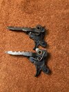
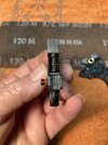
I’ve been on a bit of a crusade lately to replace the original triggers in some early, pre anti-beartrap guns with modified current issue (and in my opinion, better quality) abt modules.
There are a few things you must do to make these fit, and several things you can do to enhance function and durability.
There are a lot of details to cover in several steps along with a few “tricks”, but I’m not going to waste time and forum space unless anyone is actually interested.
So if you are interested in disassembly/reassembly, plastic mods (including getting rid of that irritating “catch” when you pull the trigger), spring mods, or reinforcement to help prevent housing separation, let me know.
Rex
 
Well, I for one am interested in it!
Hi Mark,
I was originally going 77E1056D-79C1-462C-AFD5-CCDF5936C092.jpeg 0ED762A1-4083-47F5-BD53-D7D95293905F.jpeg ED9A9275-E944-42A9-BAFB-3F0BC6BB3C15.jpeg ED9A9275-E944-42A9-BAFB-3F0BC6BB3C15.jpeg D25AE000-D934-4004-907A-54C9E90CDADB.jpeg to add this to your $15.00 Daisy thread, but because of the amount of “stuff”, and it not really being about power, I went for a separate entry.
I decided a while back that things weren’t going to improve, and I’d better just make friends with this module. After working for a while with a custom 1-piece design I realized I simply couldn’t match the trigger pull I can get from one of these.
Daisy has made some improvements over the first types.
The plastic has a different “feel” to it, it doesn’t seem as brittle and there’s a bit more of it in critical areas. They changed the shape of the abt spring retainer (first pic), and went from a butt joint to a lap joint behind the safety (2nd pic), both areas that failed a lot on early units.
Disassembly notes: First thing to go is the abt arm…I don’t object to the noise, I remove these on mine because of the spring, it’s pretty stout, and I believe the “jackhammer” effect from all that ratcheting might lead to cracking. Plus, these modules have 4 springs, 3 of which directly affect trigger pull.
I remove these by filing away the flared end flush with the arm (3rd pic) and removing the arm and spring.
I probably should mention that most of the mods I do can be done with these parts in place…I just don’t like ‘em on mine.
Next is inner spring removal, The outer one is easy (I use fingernails, as tools tend to damage these).
The best method I’ve found for the inner (sear) spring is to lift the bottom a bit with a small screwdriver and push it forward off the stub, this angles the top and makes it easier to pry out (4th pic).
Then dress the end of the brass sleeve as needed to remove it and the latch.
This is as far as I go with disassembly. I don’t split the case as they just don’t hold up on reassembly (I’ve done two, with a 100% failure rate within 100 rounds…never again !).
Next up; plastic mods, I just have to sort some pics, etc. Will try to post this later.
r
 

Attachments

  • ECA2AEB8-16C0-493E-8A99-8F48E38A4EFB.jpeg
    ECA2AEB8-16C0-493E-8A99-8F48E38A4EFB.jpeg
    238.1 KB · Views: 4
Ok, that’s a mess…I’m beginning to think this has something to do with crappy internet access out here in the sticks. I can do this in town with decent results, but out here stuff gets all jumbled up…yeesh !
 
Ok, that’s a mess…I’m beginning to think this has something to do with crappy internet access out here in the sticks. I can do this in town with decent results, but out here stuff gets all jumbled up…yeesh !
Rex, everything looks good from here... and nice photography!
 
Part 2, plastic mods:
(I’m going to try something different this time by adding pics as a separate post, maybe they’ll show up in the right order and quantity !)
If this is going into a pre-abt gun, there are some protrusions that will need to be removed, cut or filed flush with the side of the housing. These are marked in yellow in the first pic. They don’t have to be removed for an abt gun because there’s no interference, but even if you do, I recommend leaving the long part (the “shelf” that the spring rests on) for added strength (first pic).
This is also a good time to reshape the trigger blade, if desired. As issued the trigger has squared edges and an uncomfortable bump at the bottom. I address these with a file and sandpaper to remove the bump and round over the face of the trigger which gives better finger contact (pic 2).
The next part is a little harder to explain, so I hope this makes sense.
If you’re a right-handed shooter you may have noticed a “catch” when you pull the trigger partway back, this stems from the tendency to push left as you pull back. This can vary from unit to unit, ranging from nothing or barely noticeable, to bad enough to hang the trigger up where you have to release it and try again !
The culprit here is interference between the safety “flag” on the trigger and the bar on the safety.
I’ve marked this spot in yellow
(pic 3).
This can be addressed with a strip of sandpaper (I use 220 or 320, about 3/16” wide). First step is to feed the paper between these two surfaces, grit-side down, with the trigger all the way forward. Holding the paper against the housing, push the trigger in, which will sand a little off the square edge, when you pull the trigger back out the paper will come with it and will need to be repositioned for the next stroke. I repeat this about 8 or 10 times, this piece is quite thin and all you need to do is to break up the square edge (pic 4).
Next, reverse the paper (grit up), insert in same location, pull trigger all the way back, hold the paper to the trigger and pull all the way forward to start a bevel on the safety bar, reposition the paper and repeat, usually 15 or 20 times to start. It may need more removed, check it and repeat if necessary (pic 5).
Most of the material should be removed from the safety, it’s thicker, and when in the on-safe position this beveled edge fits in a socket in the r.h. housing and is of no concern. Once the “catch” is smoothed out I blow any dust out with compressed air (I’m kinda’ lazy, and rather than drag a hose over from my compressor, I usually just blow the dust out with a soda straw). Last thing I do is cut a strip from a file card and smear a very small amount of grease or shoe polish on both sides, then work it into this area a couple of times.
When you first start out, it may be too tight for the paper to fit. you might have to start with finer grit paper or reach in with an x-acto to make a little space.
One other option…the sandpaper works, but is slow. Knowing I was going to do several of these I tried a reshaped and thinned nail file. It’s faster and easier if you want to invest the effort (pic 6), blade is 3/16” wide and about.020” thick and comes almost to a knife edge on the end.
More to come…
r
 
Part 3…latch, springs, and reassembly:
The next thing I do is to polish the flat surface on the latch where the sear rides (It’s not absolutely necessary, but I’ll take whatever smoothness I can get). I start by deburring the edges with this diamond hook-sharpener, then polishing the flat with 1,000 grit paper glued to a popsicle stick, long way, not across, and finish with a bit of polishing compound on a bit of flannel.
I also do the same to the hole, and buff the outside of the brass sleeve with 4/0 steel wool.
Note that it is possible to polish the flat with the abt arm still in place. With the springs removed, the latch will flip back enough to allow (first pic).
There isn’t much, aside from cleaning, that can be done to the sear, but these don’t give much trouble anyway.
Next is a little bit of grease on the sleeve and reinstall the latch.
There are a couple of ways to secure the sleeve in the housing. The easy way is to glue a short piece of rubber hose or an o-ring on the exposed end. This is handy if you ever want to take it apart again…Being ocd, I recrown the sleeve on mine, but it’s probably more hassle than it’s worth. It’s several steps and you have to find/make some stuff. I can go into detail if interested, but would be a (long) separate post.
Springs: I tried clipping the springs to lighten the pull, but didn’t like the result, plus it’s easy to clip too much, and there’s that ragged end to deal with.
i started doing what I call the “Bic trick”, heating one end and collapsing about 3 coils (pic 2).
Using pliers (in my case, a pair of nocking pliers left over from my bow shooting days, although needlenose will work), I heat the end with a lighter just until it starts to get a little red (pic 3) and then quickly feed it over the simple forming die shown in pic 4 and push down to collapse the coils.
Sometimes this needs to be repeated to get 3 coils (both springs).
The forming die is just a scrap piece of flat whatever with a 1/8” hole, the rod is 1/8” welding rod with the end rounded over and clamped in a vise with the flat piece fitted over it and resting on the vise jaws.
The spring wire is pretty thin, and cools quickly, heating one end doesn’t seem to affect the rest of the spring.
Reinstallation: I put the collapsed ends up, the upper end of the sear spring fits in a slot, but the lower end fits over a stub. In order to install it you just about have to stab it with a small screwdriver and pry it over this stub, which would not work well with the collapsed (and somewhat softer) end. The outer spring fits over a longer stub on the top than the bottom, so I install these with the collapsed ends up as well.
The last part will deal with some additional reinforcement, which is probably a good idea if you use o-rings, etc. on the sleeve, as there isn’t a lot preventing housing separation.
r
 
Part 4…Some thoughts about reinforcement:
Glue joints in plastic are prone to failure, so this is my attempt to provide additional resistance to separation.
The first pic shows a thin (.015”) sheet metal clip glued in place surrounding an area that tends to separate. Start with a strip about .325” wide x 1” long, bend to fit with flat-jaw pliers, tap the bends flat, and trim to fit. I rough up the plastic where it fits and then glue in place with E6000, also filling in the gap at the top.
This may not totally prevent separation, but it should help.
If you have an older intact unit with the butt joint behind the safety, you can reinforce this joint also. I use a small piece of 120 grit drywall sanding screen cut to fit closely in the recess. Rough up the plastic a little and apply a thick coat of E6000, squish the screen into this and level it out a bit, add more adhesive to any bare spots, let it set up a bit. After this I wax the end of a toothpick (shoe polish) and roll it back and forth to seat the screen firmly onto the plastic and clean up any extra that squeezes out (pic 2).

I apologize for the length of these posts, but like so many things, it takes 2,000 words to describe what you could show “hands-on” in a few minutes.
I’ve tried to cover everything, but if there any questions, comments, or suggestions, you are welcome to post them here, or email me (teerex.rw@ gmail.com)
Until then, as Forrest Gump would say “That’s all I have to say about that”.

Rex
 
Thanks Mark !
I just hope some of this is useful to somebody.
In the meantime, the experiments continue…
 
Looks good, thanks!

For the newbies like me and I'm sure others ... can you define to which models these mods apply? Like I bought the Adult-sized Red Ryder BB Gun - is that work for this?

I've already done the trigger improvement work to my Avanti/Daisy model 753 and it's SUPER!
 
This should fit any of the “b” series narrow-frame guns, 105b, 111b, 1938b-Red Ryder, 1998, 1999
The only real difference is between the anti-beartrap (abt) guns and the older pre-abt models. The internal construction was changed on the later guns to accommodate the abt stuff. The Adult Ryders came after the change, so no worries.
 
Hey nice job Rex excited to see you posted some of your work very useful information I'm sure I'll have a bunch of questions when I get a few to try this out
 
Back
Top