I bought my 1952 vintage K-22 used in the mid 1990s and it has seen plenty of used since then. Like so many of those early K-22s mine is suffering from poor extraction after a few cylinders have been fired through it but the accuracy is top!

Like so many of those early K-22s mine is suffering from poor extraction after a few cylinders have been fired through it...
The screw in front of the trigger guard retains the crane.
 I love that this turned into a 'show off' thread. The K-22/Model 17 and the Colt Officer's Model match are my two grail .22 revolvers.
I bought my 1952 vintage K-22 used in the mid 1990s and it has seen plenty of used since then. Like so many of those early K-22s mine is suffering from poor extraction after a few cylinders have been fired through it but the accuracy is top!
View attachment 1063483
Yes, check on the S&W collector's site.
Just type in 5 screw S&W revolvers on your search engine.
A five screw S&W revolver has number five screw in front of the trigger guard.
Not at the base of the grip! The screw in front of the trigger guard retains the
crane.


 BTW, paid $175 for it in a local gun shop back in the early 2000's.!

You sir, are a very appreciated wealth of knowledgeHowdy
How about a few photos to explain about screws?
This is a Five Screw 38 Military and Police from the 1920s. Notice there are four screws securing the side plate to the frame.
View attachment 1063575
The fifth screw is in front of the trigger guard.
View attachment 1063576
Unlike the other four screws, which hold the side plate in place, the fifth screw held a spring and spring plunger which actuated the cylinder stop. Other brands of revolvers call the cylinder stop a bolt. This photo of a different five screw 38 M&P shows the fifth screw, and the spring and spring plunger oriented as they would go into their hole in the frame. They are pointing at the cylinder stop. It is a bit out of position, but it is the part those parts actuated.
View attachment 1063577
This is a four screw Model 27. Like all profitable companies, S&W was always on a quest to reduce the cost to make their products. The screw at the upper corner of the side plate was the first of the five screws to go. S&W found it less expensive to machine a lip on the underside of the side plate that could fit into a slot in the frame, then tapping a hole and securing the upper corner of the side plate with a separate screw. This happened during the mid 1950s on most models, varying by a couple of years per model. The side plate screw at the top of the grips is still there, but it is hidden under the grip. The screw in front of the trigger guard is also still present.on this Model 27 that shipped in 1959.
View attachment 1063578
The next screw to be eliminated was the screw in front of the trigger guard. This happened in the early 1960s on most models. This is a typical three screw S&W, a Model 17-3 that shipped in 1975.
View attachment 1063579
This photo shows the result of eliminating the screw in front of the trigger guard. A small compression spring is positioned between a hollow in the frame and the cylinder stop. This shows the actual position of the cylinder stop, with an elongated hole placed over a stud in the frame. When the action cycles, the projection on the trigger pulls the cylinder stop down, allowing the cylinder to rotate. As the trigger continues to rotate, the projection pops out of the cylinder stop, allowing the spring to pop it back up against the cylinder. Which is why most S&W revolvers have a partial turn line on the cylinder. The cylinder stop pops up about halfway between chambers and rubs against the cylinder as it finishes rotating. By the way, I much prefer taking a five or four screw Smith apart vs a three screw. It is easy to mash that spring when reassembling the revolver. Much simpler to replace the spring and plunger when they rode in a hole in the frame under a screw.
View attachment 1063580
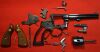
Oh, yes, I have taken enough Smith and Wesson revolvers apart to be sure that the side plate screw over the trigger guard secures the cylinder yoke in place. Here is my Model 17-3 completely disassembled. Notice there is a groove that runs around the stem of the cylinder yoke. The side plate screw over the trigger guard has two functions. In addition to holding down the front of the side plate, the tip of the screw extends into that groove in the stem of the yoke. When assembled, the yoke can rotate and is held in place by the tip of the screw extending into the groove. When the screw is removed, the yoke can be pulled forward out of the frame. This can be done for routine cleaning without taking anything else apart but that screw. If one completely disassembles the revolver it is a good idea to note which screw came out of which hole. The screw we have been talking about is often filed down to a specific length so it will not bind the yoke when snugged down. Putting the wrong screw back in that hole can sometimes cause a problem.
View attachment 1063588


Since these were Target guns shot in competition folks could order the features they wanted. When did the first long action Target hammer appear??


As far as I know, there was no 'long action target hammer'.