S&W model 10 disassembly,inspection,select repairs and reassembly - discussion

Status
Not open for further replies.

Sylvan-Forge

Member
Joined
Feb 22, 2006
Messages
1,224
Location
Fort Myers, Florida
This is mostly a summary of Jerry Kuhnhausen's excellent book; "The S&W Revolver - A Shop Manual".

The pre-checklist in the book and the checkout stickied in the revolver forum are helpful preliminary & diagnostic steps before beginning disassembly.

.

"Deep Breath"
"Patience"
"Force Nothing"

Ok, let's roll ..
:)

Disassembly :

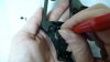
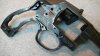
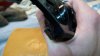
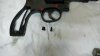
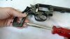
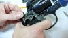
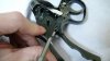
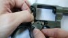
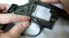
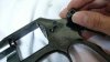
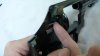
Sideplate screws removed. The first two screws, from left to right, are identical. The last is the 'Yoke Screw Assembly':
attachment.php


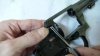
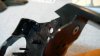
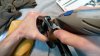
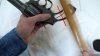
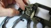
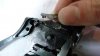
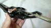
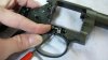
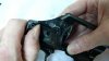
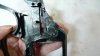
Strikeline in red. Light blows with the hammer handle set up vibrations to drive the sideplate off. Thumb lightly in place to ensure that the sideplate does not spring off and hit the floor. Mine was tight and needed a dozen smacks:
attachment.php


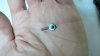
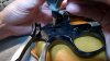
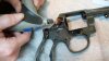
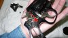
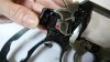
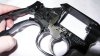
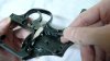
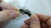
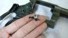
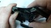
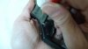
Hammer Block Safety in red. Easily removed by lifting it out. Take a look at the corrosponding guideways in your sideplate:
attachment.php


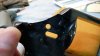
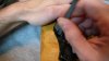
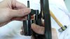
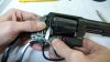
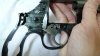
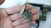
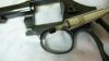
Holding the cylinder while sliding out the yoke:
attachment.php


.
 

Attachments

  • m10c-01.JPG
    m10c-01.JPG
    44.8 KB · Views: 7,559
  • m10c-02.JPG
    m10c-02.JPG
    49.6 KB · Views: 7,531
  • m10c-03.JPG
    m10c-03.JPG
    74.3 KB · Views: 7,636
  • m10c-04.JPG
    m10c-04.JPG
    48.8 KB · Views: 7,464
Last edited:
These pics were taken after S&W did the action work (mostly polishing stuff and replacing the mainspring).

Removing the mainspring tension screw. To remove the mainspring, lift it out at the bottom of the frame and carefully unhinge it from the hammer stirrup:
attachment.php


Hammer stirrup (red dot) rotated up in preperation for removal. Take care not to force it. If it hangs up while trying to rotate it, just back off and push it close to the hammer, then rotate it up:
attachment.php


Once it is rotated up, it slides right off the hammer:
attachment.php


If you want to see how things work inside, reinstall the yoke, cylinder and lightly seat the yoke screw (in red). Push down as shown to seat things properly. It locked up on me a couple times until I figured this out :p:
attachment.php


.
 

Attachments

  • m10c-05.JPG
    m10c-05.JPG
    59.5 KB · Views: 7,300
  • m10c-06.JPG
    m10c-06.JPG
    70 KB · Views: 7,267
  • m10c-07.JPG
    m10c-07.JPG
    67 KB · Views: 7,218
  • m10c-08.JPG
    m10c-08.JPG
    62.4 KB · Views: 7,192
Last edited:
Removing the hammer while holding the trigger back. Holding the trigger back allows the hammer to slip past the 'hand'. (To remove the hammer with the cylinder out, just pull the thumbpiece back).:
attachment.php


Removed the locking flag. The little nub on top is what locks the hammer. The little nub can be ground flat to disable the lock, if you so desire. Be aware, S&W will not sell locking flags, but they will install one if you send the gun to them.:
attachment.php


So far .. :
attachment.php


Rebound spring removal tool. (Note, the rebound spring is tricky to re-install . I used a deburred flat-head screwdriver to do so). This tool is made by Wheeler Engineering, #641106. (Brownells carries a different model eqipped with a handle).:
attachment.php


.
 

Attachments

  • m10c-09.JPG
    m10c-09.JPG
    63.4 KB · Views: 7,115
  • m10c-10.JPG
    m10c-10.JPG
    58.3 KB · Views: 7,093
  • m10c-11.JPG
    m10c-11.JPG
    70 KB · Views: 7,115
  • m10c-12.JPG
    m10c-12.JPG
    53.4 KB · Views: 7,111
Last edited:
Testing tool fit:
attachment.php


Pressing in and carefully lifting the rear of the rebound to just before it clears the frame pin:
attachment.php


A couple cursewords and a de-funkification of the spring after a crash landing behind the dryer and the rebound spring is now ready for picture posing :rolleyes::
attachment.php


So far .. :
attachment.php


.
 

Attachments

  • m10c-13.JPG
    m10c-13.JPG
    63.1 KB · Views: 7,040
  • m10c-14.JPG
    m10c-14.JPG
    59.2 KB · Views: 7,015
  • m10c-15.JPG
    m10c-15.JPG
    51.6 KB · Views: 6,969
  • m10c-16.JPG
    m10c-16.JPG
    64.5 KB · Views: 6,965
Last edited:
Trigger assembly removal. The hand has a spring residing within the trigger which pushes the hand foreward toward the muzzle. Gently pull the hand out of the frame window and work the trigger & hand up and out as one unit. The trigger lever may flop around or fall out.:
attachment.php


Trigger assembly with hand and trigger lever:
attachment.php


Trigger lever removal. It fits into a slot in the back of the trigger:
attachment.php


Trigger lever. Note, the little ball end (on the left) is what interfaces with the socket on the rebound slide.:
attachment.php


.
 

Attachments

  • m10c-17.JPG
    m10c-17.JPG
    54.7 KB · Views: 6,903
  • m10c-18.JPG
    m10c-18.JPG
    52 KB · Views: 6,885
  • m10c-19.JPG
    m10c-19.JPG
    42.6 KB · Views: 6,869
  • m10c-20.JPG
    m10c-20.JPG
    43.7 KB · Views: 6,867
Last edited:
Cylinder stop and spring removal. Press the cylinder stop down and hold it with your fingernail. (I grew mine out just for this:p):
attachment.php


Get a thin screwdriver (should deburr edges of screwdriver to keep from marking stuff up) and slide it underneath the cylinder stop and slowly work it up. If your careful you can catch the spring against the frame rather than launching it:
attachment.php


Cylinder stop and spring. Onward and upward!:
attachment.php


Removed the thumbpiece nut:
attachment.php


.
 

Attachments

  • m10c-21.JPG
    m10c-21.JPG
    66.2 KB · Views: 6,809
  • m10c-22.JPG
    m10c-22.JPG
    67.5 KB · Views: 6,779
  • m10c-23.JPG
    m10c-23.JPG
    55.1 KB · Views: 6,769
  • m10c-24.JPG
    m10c-24.JPG
    40.7 KB · Views: 6,768
Last edited:
Lifting off the thumbpiece:
attachment.php


Take a look at the 'cylinder bolt' before removal. Note the pivot end is inside of the recoil plate, so take care not to bend it while removing.
In the picture I'm pushing the hammer-stop portion of the cylinder bolt backwards and easing it out of the frame towards the camera.
attachment.php


If your careful you can catch the plunger against the frame and lessen the risk of launching it and the spring:
attachment.php


Cylinder bolt with spring and plunger (the protrusion on the left of the cylinder bolt itself is referred to as the 'hammer stop', on the far right is the 'pivot' and on the back is where the thumbpiece nut threads to)
attachment.php


.
 

Attachments

  • m10c-25.JPG
    m10c-25.JPG
    58.3 KB · Views: 6,723
  • m10c-26.JPG
    m10c-26.JPG
    51.4 KB · Views: 6,694
  • m10c-27.JPG
    m10c-27.JPG
    46.5 KB · Views: 6,688
  • m10c-28.JPG
    m10c-28.JPG
    40.9 KB · Views: 6,686
Last edited:
Using the 'bugger scoop' tool to lift out the end of the lock spring. Once it's off a bit, just walk it out the rest of the way.:
attachment.php


Used the lock key provided with the gun to get the lock cam centered and used a flat head screwdriver to slide the locking fork toward the muzzle.:
attachment.php


The locking cam plops right out:
attachment.php


There 'tis (the locking cam thing):
attachment.php


.
 

Attachments

  • m10c-29.JPG
    m10c-29.JPG
    43.3 KB · Views: 6,661
  • m10c-30.JPG
    m10c-30.JPG
    63.6 KB · Views: 6,652
  • m10c-31.JPG
    m10c-31.JPG
    39.3 KB · Views: 6,623
  • m10c-32.JPG
    m10c-32.JPG
    49 KB · Views: 6,627
Last edited:
Sliding out the locking fork:
attachment.php


Safety lock assembly. :scrutiny: 
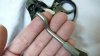
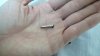
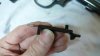
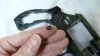
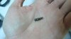
(Looks like it could summon unholy spirits or something):
attachment.php


Firing pin retaining pin slips out easily with some tweezers:
attachment.php


Firing pin and firing pin spring.
attachment.php


.
 

Attachments

  • m10c-33.JPG
    m10c-33.JPG
    45.3 KB · Views: 6,605
  • m10c-34.JPG
    m10c-34.JPG
    42.6 KB · Views: 6,583
  • m10c-35.JPG
    m10c-35.JPG
    53.8 KB · Views: 6,594
  • m10c-36.JPG
    m10c-36.JPG
    41.2 KB · Views: 6,585
Last edited:
Nicely nicely. Good, clear and well lit photos too. Thank you.
How do you like the 10? How does it shoot?
 
Thank you, MartinS. Most welcome. :)

It's a stretch for me to reach the trigger proper, but with small grips it's feeling better. I'd say it ranks as fair/ok (for this day and age) as far as overall build quality. The barrel face had a litle metal rolled off the left side, making for a sharp edge and is not perfectly square to the bore or cylinder. It shoots a tight group, but prints a little to the right. The trigger frame pin is slightly bent down which cocks the trigger over to the left a little bit and the there is a small chunk out of the frame near the hammer opening.
As noted, there was quite a bit of rust inside.

S&W took the edge off the barrel face but did not set the barrel back and true the barrel face (I should have asked them to).
They must have missed the trigger pin being bent (I did too) when doing the action work.
I didn't say anything about the chunk and neither did they.
They did get most of the rust out and the action work was pretty nice.

It's currently submerged in an oil bath while I wait for some tools to show up.

:D

.
 
I'd like to add a note:
I'm not super familiar with revolvers, so when I was taking stuff apart I would often times put them right back in again to commit the procedure to memory.

As an example, when I popped the sideplate and pulled out the hammer block, I went and put it all back together again and tested function just to make myself sure.

Did the same thing with the rebound slide. And hammer. And trigger.

Anyhoo.

:)
 
Thank you so much for taking the time to make this post. It's very helpful. I've recently been tinkering with my revolvers. I purchased the Kuhnhausen book and this thread is a great supplement.

I am going to save this link.

RWK
 
Thanks Chester!

1KPerDay, if I can do it, anybody can. Like I said, I reassemble nearly every part or assembly to keep myself in check. I'm a little verbose, so maybe that makes it seem harder than it really is.

parisite & .38 Special, thanks for the votes of confidence. I'd hope if I screw something up royally that this thread would disappear into obscurity rather than be stickied! :p

NCBeagle, thanks for the kind words, just defer to Kuhnhausen before me, I do! :D

.
 
Clean and inspect frame :

Frame pins (4) highlighted in red. All except the trigger pin appear smooth and straight. Since S&W has already done the action job, I'm just going to leave the trigger pin alone. Maybe one day I'll grab some new parts, straighten out that pin and do the action job myself.:
attachment.php


Rolled metal edge on safety lock hole. Since some of the edge is breaking free, I'll clean it up.:
attachment.php


I know, I know :rolleyes: I was very careful! :D:
attachment.php


Used a round file to clean up the inside of the hole after using the dremel.:
attachment.php


.
 

Attachments

  • m10c-37.JPG
    m10c-37.JPG
    91.8 KB · Views: 6,401
  • m10c-38.JPG
    m10c-38.JPG
    42.2 KB · Views: 6,371
  • m10c-39.JPG
    m10c-39.JPG
    62.2 KB · Views: 6,364
  • m10c-40.JPG
    m10c-40.JPG
    49.1 KB · Views: 6,353
Last edited:
A chunk out of the frame near the hammer slot and a span of thin and weak metal that breaks away under the fingernail. It wouldn't be good to have this possibly end up in the action.:
attachment.php


The thin metal span was rounded so I used the dremel to flatten the span so I could get the file to it.:
attachment.php


Flat file with safe edges. Not much room to work.:
attachment.php


Polishing up with a felt wheel and polishing compound. Verified there is no metal rolled over to block the hammer's access to the firing pin or in the notch where the sideplate tab fits.:
attachment.php


.
 

Attachments

  • m10c-41.JPG
    m10c-41.JPG
    45.9 KB · Views: 6,353
  • m10c-42.JPG
    m10c-42.JPG
    57.8 KB · Views: 6,337
  • m10c-43.JPG
    m10c-43.JPG
    55.1 KB · Views: 6,326
  • m10c-44.JPG
    m10c-44.JPG
    79.7 KB · Views: 6,329
Last edited:
Status
Not open for further replies.
Back
Top