S&W model 10 disassembly,inspection,select repairs and reassembly - discussion

Status
Not open for further replies.
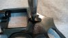
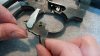
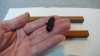
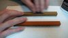
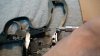
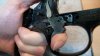
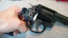
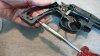
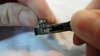
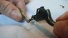
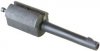
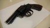
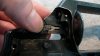
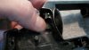
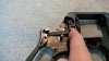
Insert firing pin with spring. The notched part of the firing pin faces down.:
attachment.php


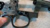
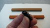
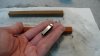
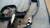
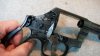
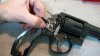
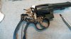
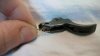
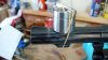
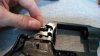
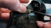
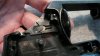
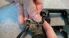
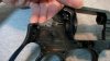
While holding the firing pin in, insert the firing pin retaining pin. It's only seated with finger pressure and it's done.:
attachment.php


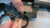
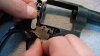
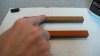
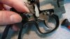
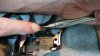
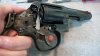
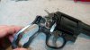
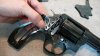
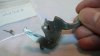
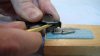
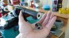
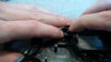
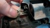
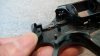
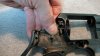
If you decide to install the lock parts, stick the fork in as shown. Since the tang part of the fork was likely bent a little bit during removal, install it with the tang bend facing out to ease spring install. Slide it toward the muzzle with a screwdriver to clear the hole for the lock cam.:
attachment.php


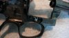
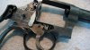
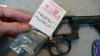
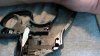
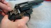
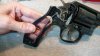
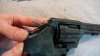
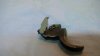
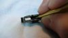
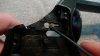
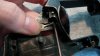
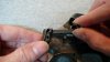
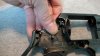
Lock cam slips right in.:
attachment.php


.
 

Attachments

  • m10c-97.JPG
    m10c-97.JPG
    72.5 KB · Views: 1,910
  • m10c-98.JPG
    m10c-98.JPG
    48.9 KB · Views: 1,894
  • m10c-99.JPG
    m10c-99.JPG
    48 KB · Views: 1,897
  • m10c-100.JPG
    m10c-100.JPG
    52.5 KB · Views: 1,895
Last edited:
Slide the fork against the cam to ease spring install.:
attachment.php


Prop the spring up and catch the fork's tang with it.:
attachment.php


Work the spring onto the tang with your finger or a screwdriver.:
attachment.php


Finish up by pressing the spring down firmly into its recess.:
attachment.php


.
 

Attachments

  • m10c-101.JPG
    m10c-101.JPG
    52.3 KB · Views: 1,880
  • m10c-102.JPG
    m10c-102.JPG
    60.4 KB · Views: 1,881
  • m10c-103.JPG
    m10c-103.JPG
    55.5 KB · Views: 1,874
  • m10c-104.JPG
    m10c-104.JPG
    52.8 KB · Views: 1,877
Last edited:
There 'tis. Can you tell I got hold of some stones? Killed a stupid ridge along the slideplate junction!:
attachment.php


Set the locking flag into its recess in the frame. Note the notch (yellow circle); this is where you can stick a needle or safety pin to catch the flag spring and nudge it into the small recessed slot in the frame (red line).:
attachment.php


Cylinder bolt install, pic 1. Stick a little lube in there to help the plunger slide against the frame as the pivot end of the cylinder bolt is lowered into place.:
attachment.php


Cylinder bolt install, pic 2:
attachment.php


.
 

Attachments

  • m10c-105.JPG
    m10c-105.JPG
    63.2 KB · Views: 1,881
  • m10c-106.JPG
    m10c-106.JPG
    56.5 KB · Views: 1,879
  • m10c-107.JPG
    m10c-107.JPG
    58.5 KB · Views: 1,872
  • m10c-108.JPG
    m10c-108.JPG
    78.1 KB · Views: 1,869
Last edited:
Cylinder bolt install, pic 3:
attachment.php


Cylinder bolt install, pic 4:
attachment.php


Cylinder bolt install, pic 5:
attachment.php


Cylinder bolt install completed.:
attachment.php


.
 

Attachments

  • m10c-109.JPG
    m10c-109.JPG
    78.6 KB · Views: 1,869
  • m10c-110.JPG
    m10c-110.JPG
    76.4 KB · Views: 1,867
  • m10c-111.JPG
    m10c-111.JPG
    77.5 KB · Views: 1,860
  • m10c-112.JPG
    m10c-112.JPG
    69.1 KB · Views: 1,859
Last edited:
Install thumbpiece. Just snug it down, don't torque it :):
attachment.php


Set the cylinder stop on its frame pin with the spring captured against the frame.:
attachment.php


Coerced into its place by a deburred flat-head screwdriver.:
attachment.php


A little nudge to the end of the spring to get it sqaure to the stop and it's done.:
attachment.php


.
 

Attachments

  • m10c-113.JPG
    m10c-113.JPG
    69.3 KB · Views: 1,857
  • m10c-114.JPG
    m10c-114.JPG
    83.4 KB · Views: 1,855
  • m10c-115.JPG
    m10c-115.JPG
    78 KB · Views: 1,854
  • m10c-116.JPG
    m10c-116.JPG
    72.5 KB · Views: 1,856
Last edited:
Trigger and hand with trigger lever pushed up prior to installation.:
attachment.php


Carefully pull the hand back while installing the trigger on its frame pin.:
attachment.php


So far...:
attachment.php


.
 

Attachments

  • m10c-117.JPG
    m10c-117.JPG
    63.3 KB · Views: 1,850
  • m10c-118.JPG
    m10c-118.JPG
    64.5 KB · Views: 1,850
  • m10c-119.JPG
    m10c-119.JPG
    89.6 KB · Views: 1,852
Last edited:
Rear view of rebound slide. S&W did work on this. All edges and corners are rounded and polished smooth.:
attachment.php


Another view of the rear of the rebound slide. Note that the edges on the outside or sideplate side of the rebound slide are unfooledaroundwith. I guess that's just fine so long as there is no edge contact with the sideplate.:
attachment.php


The backside or frame side of the rebound slide was formed with a rounded lower edge and S&W rounded and polished the front corner edges.:
attachment.php


Uh oh.:
attachment.php


.
 

Attachments

  • m10c-120.JPG
    m10c-120.JPG
    32.3 KB · Views: 1,850
  • m10c-121.JPG
    m10c-121.JPG
    43.3 KB · Views: 1,846
  • m10c-122.JPG
    m10c-122.JPG
    33.1 KB · Views: 1,841
  • m10c-123.JPG
    m10c-123.JPG
    58.4 KB · Views: 1,840
Last edited:
Medium-Fine India stone in the background and Fine-Fine India stone in the fore. Schleping some honing oil on.:
attachment.php


:eek: Just polishing up the bottom is all :D :
attachment.php


Not going to go any farther even though those couple low places are bugging me. Go too far and end up with the frame pin striking the rebound slide=ruination! I restrained m'self, thankfully.:
attachment.php


Cleaned up and ready to install. Showing the front of the rebound slide. On the very top is the rebound's hammer seat, in the middle is the nose, on bottom is the socket where the trigger lever ball rides.:
attachment.php


.
 

Attachments

  • m10c-124.JPG
    m10c-124.JPG
    48.2 KB · Views: 1,842
  • m10c-125.JPG
    m10c-125.JPG
    53.7 KB · Views: 1,844
  • m10c-126.JPG
    m10c-126.JPG
    50.3 KB · Views: 1,839
  • m10c-127.JPG
    m10c-127.JPG
    77.1 KB · Views: 1,840
Last edited:
Since things are slicked up, I'm going to go with a lighter rebound spring. (After testing, I switched it for a 12lb. spring. Might even go to an 11lb. later).:
attachment.php


Preparing to use a flat head screwdrive to push the sping in. Got a box set up to catch the spring in case it slips.:
attachment.php


If you hold your mouth just right and say a prayer to the spring god, you can push the rebound down while pushing in with the screwdriver. The rebound's frame pin will push the screwdriver out of the way and the spring will catch against the frame pin (in theory of anyway :rolleyes:). The lower part of the spring's coil is on the post but the top is off, threatening that it will launch itself.:
attachment.php


Using just the lower corner of the screwdriver's tip to push the top part of the coil clear while pushing down on the rebound.:
attachment.php


.
 

Attachments

  • m10c-128.JPG
    m10c-128.JPG
    73.4 KB · Views: 1,833
  • m10c-129.JPG
    m10c-129.JPG
    69.8 KB · Views: 1,837
  • m10c-130.JPG
    m10c-130.JPG
    85.7 KB · Views: 1,836
  • m10c-131.JPG
    m10c-131.JPG
    69.7 KB · Views: 1,830
Last edited:
There!
attachment.php


Verifying function and checking that the trigger lever is seated properly in the rebound slide.:
attachment.php


Added some lube.:
attachment.php


Yoke and cylinder into the frame again or hold the thumbpiece back to allow for hammer install.:
attachment.php


.
 

Attachments

  • m10c-132.JPG
    m10c-132.JPG
    80.9 KB · Views: 1,830
  • m10c-133.JPG
    m10c-133.JPG
    55.3 KB · Views: 1,822
  • m10c-134.JPG
    m10c-134.JPG
    75.2 KB · Views: 1,831
  • m10c-135.JPG
    m10c-135.JPG
    71.2 KB · Views: 1,825
Last edited:
Hold the trigger back (and thumbpiece if cyl. not in) and install the hammer.:
attachment.php


Hammer installed.:
attachment.php


Hammer stirrup install, pic 1:
attachment.php


Hammer stirrup install; rotate it down to complete.:
attachment.php


.
 

Attachments

  • m10c-136.JPG
    m10c-136.JPG
    75.2 KB · Views: 1,797
  • m10c-137.JPG
    m10c-137.JPG
    78 KB · Views: 1,800
  • m10c-138.JPG
    m10c-138.JPG
    79.4 KB · Views: 1,794
  • m10c-139.JPG
    m10c-139.JPG
    82 KB · Views: 1,797
Last edited:
With the mainspring sorta lying parallel to the frame, finesse the mainspring into the stirrup first, then guide it into the grip.:
attachment.php


With the main spring centered squarely in the grip, tighten down the strain screw.:
attachment.php


Make sure to remove the yoke screw if it's in.:
attachment.php


Hammer block shown in its 'at rest' position. It is set onto the pin that's attached to the rebound slide. Make sure to push it all the way up between the hammer and frame.:
attachment.php


.
 

Attachments

  • m10c-140.JPG
    m10c-140.JPG
    81.4 KB · Views: 1,803
  • m10c-141.JPG
    m10c-141.JPG
    84.7 KB · Views: 1,803
  • m10c-142.JPG
    m10c-142.JPG
    91.9 KB · Views: 1,807
  • m10c-143.JPG
    m10c-143.JPG
    81.4 KB · Views: 1,810
Last edited:
It's actually easier to install the sideplate with the gun tilted so that the hammer block does not slip out of its 'at rest' position. If it shifts it will block the sideplate from seating correctly. The hammer block needs to fit within its guideways on the sideplate.

This pic is just to show the tab at the top of the sideplate, which goes into the frame first.

After the top tab is in, press the sideplate in at the yoke screw end, then press it down in the middle while working toward the grip, pressing as you go. If you feel like it's catching, it's probably hitting the hammer block. Pop the plate as shown at the beginning of the thread and try again. If you have a real tight sideplate like I do, practice without the hammer block installed until you get a good feel for it. The shiney metal was from stoning away a ridge on the frame and sideplate.:
attachment.php


.
 

Attachments

  • m10c-144.JPG
    m10c-144.JPG
    56.6 KB · Views: 1,798
Last edited:
Here's a pic of 'er all in one piece.
attachment.php


.

I've taken it down a good four times after dry fire sessions for cleaning n' lube and found a few more things to tinker with, so I'll try and detail those 'fixes' soon.

Hopefully it won't be too long for the forcing cone cut + velocity comparison and I'm looking into using a jig for barrel setback as well as some other nifty jobbers.

:D

.
 

Attachments

  • m10c-145.JPG
    m10c-145.JPG
    43.2 KB · Views: 1,783
Thanks rainbowbob!
I haven't shot it since going into it. It will probably bug me to no end to see it hitting to the right :p so I'll just shoot it through the chrono and not think about hitting anything until I set the barrel back and get the sights lined up proper (they over-torqued the barrel :rolleyes:).

.
 
Great work! I've always wondered how and if I could work on my revolvers.
Have you done anything yet with the shiney metal on the sideplate?
Take Care,
Zac
 
At the feet of a Master.
Do you assemble all the parts dry or is there some lube I do not see?
 
A tip about rebound spring installation I have discovered:

If you don't have the specialized tool, the next best option is a small center punch - one small enough to fit inside the spring cylinder buy not too small so as to pass down the center of the spring. A tapered one works well as it catches on the spring even if the tip is smaller than the spring center. You can depress the spring nicely with this, without fear of your tool sliding or popping out sideways because of the spring tension, losing your spring or scratching your work. Once past the post, you just push it down with your thumb. For those not following, what I am suggesting is a punch like the first one pictured in the Wikipedia entry:

http://en.wikipedia.org/wiki/Punch_(engineering)

Thanks for this post - nice job.
 
This was the most informative post I have ever seen on the entire internet. Thank you very much.
 
aHFo3, S&W actually replaced the frame when it was sent in for repair (broken hammer stud) so now it looks great, though I still plan to duracoat it.
Thanks for the compliment.

MartinS, shucks, thanks. I'm always slopping around in ATFluid, so a small amount gets rubbed on the parts during handling.

Oro, I couldn't view the wikipedia page, but it sounds like a good idea, thanks for sharing and your welcome.

boatguy, thanks for that and your welcome.

.

S&W replaced the frame, turned the barrel back proper and recut the forcing cone. Kudos to S&W for treating a customer good.
Probably just as well that I don't get into setting a barrel back without a lathe or experience :uhoh:

Bead blast should be done after Christmas followed by some duracoating :)

A fellow may be looking for help with the hand spring, which I'll try and detail here.

.

Happy holidays!

.
 
Trigger & Hand Assembly Detail

Shown in red is the short leg of the hand spring.:
attachment.php


Hand spring orientation.:
attachment.php


From the rear of the trigger, the long leg of the hand spring is shown in yellow. It rides in front of the smaller diameter hand pin and is under tension. The short leg of the spring (not shown) is in its recess. The main coils (yellow zig-zag) are set in a cupped seat.:
attachment.php


View of the hand pins and trigger.:
attachment.php


.
 

Attachments

  • m10c-146.JPG
    m10c-146.JPG
    47.9 KB · Views: 1,642
  • m10c-147.JPG
    m10c-147.JPG
    51.5 KB · Views: 1,638
  • m10c-148.JPG
    m10c-148.JPG
    44.6 KB · Views: 1,628
  • m10c-149.JPG
    m10c-149.JPG
    51.4 KB · Views: 1,626
Last edited:
Hand spring going in. Guide the short leg into the recess and the main coils into the seat. Note: The spring is retained by its seat in the trigger and the pressure exerted on it by its legs when assembled. There's no pins going through the main coils.:
attachment.php


Using a 1/8" brass punch to align the coils in its seat. Note the long leg is along the right wall in the trigger.:
attachment.php


Some duct tape on a 1x2 holding the hand + lowering the trigger over the hand pins while depressing the long spring leg with the punch. Push the long spring leg in far enough so that it will exert on the smaller diameter hand pin when assembled.:
attachment.php


.

Verify the hand has spring tension directing it toward the front of the trigger. The full fore and aft movement is about 90 degrees. Mine locks in place when when pulled fully aft. I notice the end of the long leg drags on the main hand pin when its in the fore position but this doesn't seem to be a problem.

.

Best regards and merry Christmas to all.
:)

.
 

Attachments

  • m10c-150.JPG
    m10c-150.JPG
    48.9 KB · Views: 1,590
  • m10c-151.JPG
    m10c-151.JPG
    42.6 KB · Views: 1,589
  • m10c-152.JPG
    m10c-152.JPG
    45.8 KB · Views: 1,587
Last edited:
Cut Barrel

A four-inch barrel is a little too long for me to mobilize and sit with comfortably, so I decided to hack a little off. I started to look for a nice bandsaw, but right now there's just no room (or money) for it, so I went with using a hacksaw. I bought some fresh blades at the local Northern Tool and ended up only needing to use one blade to get through the barrel. The blade is a Lenox Thin Metal 32 TPI Bi-Metal 232HE. This honey is still sharp too.

I wanted to plug the bore to keep out the chips and ended up putting an X-Ring rubber bullet in backwards a little over 3/4" down the bore.:
attachment.php


I used an LE Wilson case holder for a visual reference and sometimes as a physical guide for helping keep the blade somewhat aligned. A tiny machined square likely would have served better.:
attachment.php


About two-thirds of the way down I started to angle the cut away from the muzzle a bit, but some filing done after this pic set it back to (mostly) square.:
attachment.php


To see if I was done cutting, I cleaned it up, put it back together and toted it around a bit. I was able to sit down without the muzzle hitting the seat. Draw speed and balance are much improved.:
attachment.php


The barrel is about 3.2" now, and will probably be around 3.1" after facing, crowning, some file radiusing and final polishing.

Time to order up the cutters!

(update coming soon)

:)

.
 

Attachments

  • m10c-153.JPG
    m10c-153.JPG
    54.7 KB · Views: 1,557
  • m10c-154.JPG
    m10c-154.JPG
    57.5 KB · Views: 1,554
  • m10c-155.JPG
    m10c-155.JPG
    67.2 KB · Views: 1,554
  • m10c-156.JPG
    m10c-156.JPG
    36.2 KB · Views: 1,557
Status
Not open for further replies.
Back
Top