Why do the specification for the 20mm rail look so off the wall?

Status
Not open for further replies.

Payload

Member
Joined
Apr 18, 2013
Messages
16
Now I assume this has something to do with the contact points between the rail and whatever you hook to it, but the way in which the dimensions are defined is just bizarre to my understanding.

M1913A_Rail_CrossSection.svg


Can anyone explain to me why they chose such a strange way to define everything? Shouldn't they look more like the attached image (all dimensions are in mm)
 

Attachments

  • Untitled.jpg
    Untitled.jpg
    19.4 KB · Views: 15
I probably would have used profile tolerances rather than true position, but it looks ok to me. Do you have much experience with GD&T?
 
I have not been able to see the first photo since it was posted today so I don't know what the question is??

All I see is a black box with an X in it.

rc
 
Very, Very little experience with GD&T. I started with a college course and work with it a little as a hobby. I should have used Profile.
 
Some comments after a quick look:

- As noted above, it's not really appropriate to use position for those features.
- The .835 dimension does not appear to be fully located.
- I would have used a high/low or + 0.000 / -0.XXX for one sided tolerances for clarity.
- Angles are basic, but tolerance/position is not defined.
- -C- may not be an appropriate datum (theoretically exact point, axis, or plane).

It's definitely interesting, but I don't have the other views to fully see the context.
 
I wasn't commenting on the dimensions but rather how they are placed in the original I sketched that rail outline in all of two minutes, I didn't even bother with the tolerances because it's a quick sketch. What I'm getting is "Why are there two reference lines just running through what I assume to be midpoints on the outer < > portion of the rail?" It may have to do with how exactly you ensure alinement of the top plane with the lower post which just so happens to be narrower than the plane (Sometimes I would really love to know what they were thinking when they cook this stuff up.) For the record, I hate the 20mm rail in general.
Attaching a new sketch, still no tolerances. Why? Because I don't intend to manufacture it so I won't waist the effort.

By the way, I remember a small chart with the standards for tightest sliding fit, rotational fit, and press fit. I can't find that chart anywhere so if you could send my the numbers if you know them I would be most appreciative.

PS. Solid Works get's grumpy if the dimensions aren't tied to an absolute "origin" point.
 

Attachments

  • Untitled.png
    Untitled.png
    55.6 KB · Views: 6
Last edited:
Sorry, didn't understand what you were asking - I'll take another go.

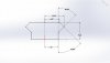
In the last drawing, the top plane is definitely positioned in relation to the bottom post. I imagine it would be important to do this to make it approximately centered so accessories fully seat on the rail. Being skewed too much one way or the other would either cause the corner of the rail to hit the mount or not provide enough area to fit securely. In short, the position of the lower 45 degree angles with respect to the top plane seems to be of particular importance, while the position of the bottom post only needs to be such as to prevent it from interfering with the previous two features.

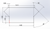
Now, on the first drawing, I have no idea why the midpoint of the bottom 45 degree surface is positioned in reference to the top 45 surface, and vice versa. Unless there is an accessory that clamps solely on the angles, the upper surface seems geometrically unimportant. The dimensions based on these midpoints seem very strange to me. Again, it's hard to tell exactly what the intent was since the GD&T on Figure 1 just seems wrong in a few places.
 
well there is definitely enough there to draw a simulated matching part, and to establish the tolerance envelope. Its like the old way of defining tapers with a datum points.
 
Actually the original standards said the <> were the only surfaces that were supposed to be load bearing (again, Why?.) This doesn't explain why when NATO standardized it and changed it to use only the bottoms of the <> and the top plane that they still use this strange way of dimensioning. Perhaps they're going for backwards compatibility. Thanks for the fit classes by the way.
 
Last edited:
Status
Not open for further replies.
Back
Top